Fluid Components International ST75 PDA Software User Manual
Page 11
FLUID COMPONENTS INTERNATIONAL LLC
ST50/ST75 PDA SOFTWARE
Configuring and Setting up the Pulse Output Channels
• The Pulse Output Channels are used to Provide Totalizer and Process Alarm information. Totalizer information is provided
as a voltage pulse, and Alarm information is provided as a Voltage “State Transition”; Low-To –High or High-to-Low.
There are 2 channels; Channel 1 is a Source Channel, and Channel 2 is a Sink Channel. (See ST50/ST75 Installation
Instructions for information on how to connect to these 2 channels).
• From the Setup Menu, tap on the “Output Config” button to open the setup screen for the ST50/ST75 Analog Channel
selection, and the Pulse Output channel setup.
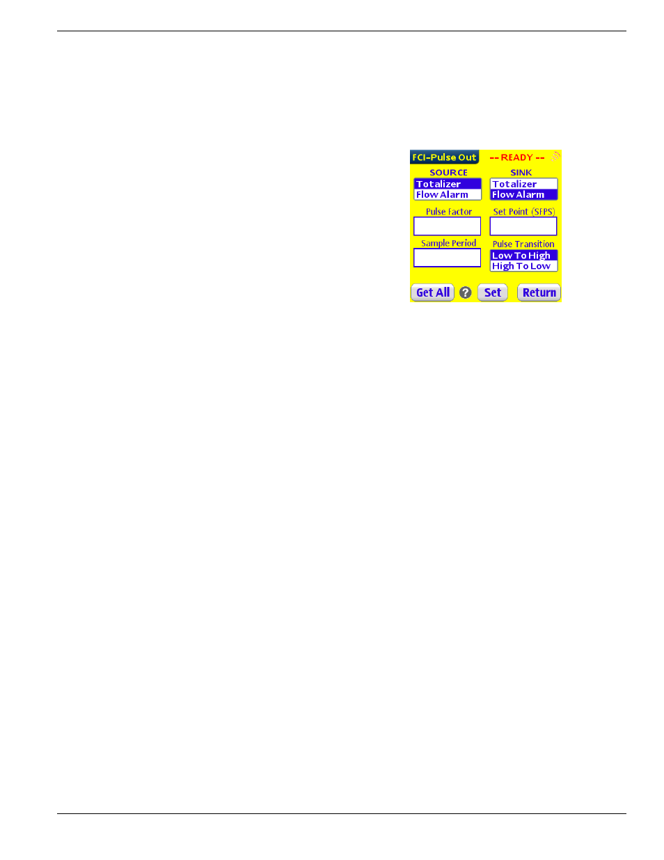
• Tap on the “Pulse Out Setup” button to open the Pulse Output
Channels Configuration screen.
• Tap On the “Get All” button to read the current setup of the
ST50/ST75.
• Chose the signal to be assigned to the Source Channel.
• Choose the signal to be assigned to the Sink Channel.
• Select and enter the new values for “Pulse Factor”, and “Sample
Period”. In most cases these values do not do change from the
factory settings.
• If the “Flow Alarm” has been selected, then also select the pulse
transition format Low-to-High or High-to-Low.
• Select the Flow Alarm set point (It is selectable in SFPS).
• Some Definitions
Sample Period: This is the “Pulse Output” channel update rate. Pulse output is not a continuous outputting signal, but a new
value is updated based on the Sample Period parameter.
Pulse Factor:
This is the equivalency number to the corresponding instrument volumetric flow units. (i.e. 1 pulse is equal
to 1 NCMH for a factor of 1, if NCMH are the volumetric units selected.
This page is subject to proprietary rights statement on last page.
9 06EN003372
Rev.
A