Regelkarte, Deutsch, Position der steckbrücken festlegen – Burkert Type 3005 User Manual
Page 49
49
Installation
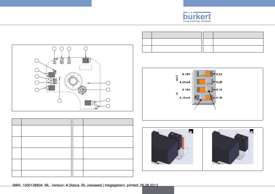
9.3. regelkarte
Für Drehantrieb mit analogsteuerung
H
G
D
E
C
F
N
B
I
A
M
L
K
J
Bild 22: Regelkarte (24V DC)
no.
Bezeichnung
no.
Bezeichnung
a
24 V DC
Spannungsversorgung
h
K2 Steckbrücke
B
Anschlussklemmen
Signalgeber
i
K3 Steckbrücke
c
Anschlussklemmen
Rückmeldung
J
Grüne und rote LED´s
D
Einstellknopf
k
Gelbe LED: anzeige
Stromversorgung
e
Einstellknopf
l
Potentiometer
no.
Bezeichnung
no.
Bezeichnung
F
Einstellknopf
m
Anschluss Motor
g
K1 Steckbrücke
n
Anschluss Heizwiderstand
9.3.1. Position der steckbrücken festlegen
ON
(eingeschaltet)
OFF
(ausgeschaltet)
Bild 23: Steckbrücke K1 / K2
Bild 24: Steckbrücke K3 OFF
Bild 25: Steckbrücke K3 ON
Typ 3005
deutsch
See also other documents in the category Burkert Accessories for water:
- Type 0125 (15 pages)
- Type 0121 (4 pages)
- Type 0330 (2 pages)
- Type 0331 (4 pages)
- Type 6012 (4 pages)
- Type 0127 (18 pages)
- Type 0131 (5 pages)
- Type 0141 (5 pages)
- Type 0142 (12 pages)
- Type 0145 (3 pages)
- Type 0174 (5 pages)
- Type 0212 (2 pages)
- Type 0211 (5 pages)
- Type 0212-B (18 pages)
- Type 0250 (64 pages)
- Type 0253 (2 pages)
- Type 0255 (15 pages)
- Type 0355 (2 pages)
- Type 0255 (2 pages)
- Type 8006 (34 pages)
- Type 8640 (2 pages)
- Type 8640 (55 pages)
- Type 8640 (119 pages)
- Type 0256 (15 pages)
- Type 0256 (2 pages)
- Type 0258 (72 pages)
- Type 0262 (5 pages)
- Type 0273 (6 pages)
- Type 0280 (5 pages)
- Type 0280 (2 pages)
- Type 0280 (12 pages)
- Type 0281 (2 pages)
- Type 0282 (2 pages)
- Type 0283 (2 pages)
- Type 0286 (4 pages)
- Type 0287 (15 pages)
- Type 0290 (2 pages)
- Type 0290 (14 pages)
- Type 0293 (18 pages)
- Type 0300 (6 pages)
- Type 0301 (6 pages)
- Type 0311 (2 pages)
- Type 0312 (6 pages)
- Type 6519 (3 pages)
- Type 6519 (4 pages)