Burkert Type 3005 User Manual
Page 17
17
Installation
procedure:
Fig. 10: Standard installation
→
Ensure that the ball valve / the flap valve is in its closed position.
→
Carefully connect the rotary actuator to the shaft of the ball valve
/ flap valve.
When connecting the rotary actuator, ensure that it is not
twisted and that the fastening threads of the rotary actuator
are covered by the fastening bores of the ball valve / flap
valve.
→
Screw the fastening screws into the fastening threads of the rotary
actuator and tighten them firmly (max. 3 Nm).
8.2.2. set mechanical end position limit
(actuators 100 - 1000 nm)
The mechanical end position limits have been preset at
the factory and glued on with Loctite. However, they can
be adjusted by turning the screws M8 Pos. 17. Then the
nuts must be glued on again.
→
Loosen the M8 nuts on the mechanical limit stops 17 (see “Fig. 1”
and “Fig. 3”) and adjust the mechanical end position limits.
→
Glue nuts on again with Loctite (e.g. Loctite 577).
8.2.3. adjusting limit switch contacts
The two upper limit switch contacts have been set to
0 - 90° at the factory.
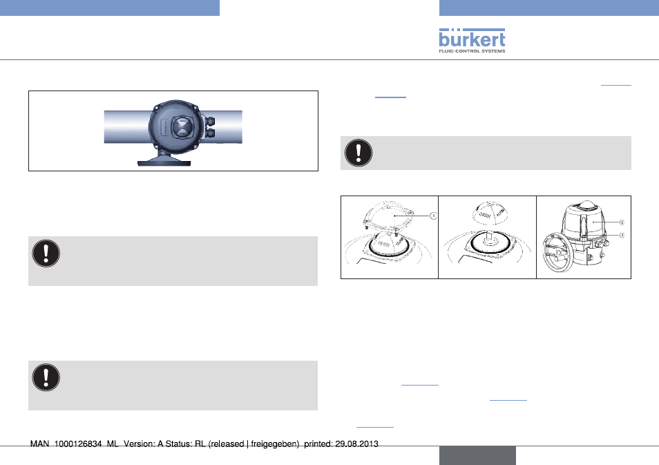
removing position indicator and hood
Fig. 11: Removing
glass hood
Fig. 12: Removing
position
indicator
Fig. 13: Removing
hood
procedure:
→
Remove glass hood of the position indicator 1 including the sealing
ring by loosening the four fastening screws and remove the glass
hood (see “Fig. 11”).
→
Remove position indicator (see “Fig. 12”).
→
Remove hood 2 by loosening the four fastening screws 3 (see
“Fig. 13”).
english
Type 3005