English, T 250 ma – Burkert Type 8025 User Manual
Page 41
41
Wiring
Type 8025 / 8035
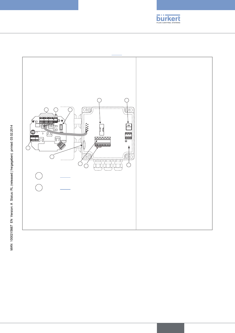
8.7.2. Wiring the 8025, wall-mounted version, 115/230 V Ac, without relays
→
Before wiring the device, obey the instructions of chap. "8.7.1".
Supply
12..36Vdc
NPN SENSOR
1 PULSE INPUT
2 -
3 +
4 NC
SUPPLY
1
2
3
4 PE
REL1
REL2
FLOW SENSOR
FLOW SENSOR
COIL
NPN
COIL SENSOR
1
2
3 NC
4 NC
L+
L-
PE
P-
P+
NC
L+
L-
PE
P-
P+
Iout
PULSE
OUTPUT
Without
With
Relays
230V
L N
230V
T 250 mA
5 6 7 8 9 10
L N
230V
{
7
5
3
8
2
1
A
B
4
6
PE
Switch A : see chap. "8.3.1"
Switch B : see chap. "8.3.3"
terminal block 1
NC: not connected
L+ (red wire, factory wired)
L- (green wire, factory wired)
PE: wiring of the PE between the main board
and the protection board
P- (brown wire, factory wired)
P+ (white wire, factory wired)
terminal block 2 pe
Shield wiring (green/yellow wire, factory wired)
time-delay fuse 3: fuse to protect the
115 V AC or 230 V AC power supply
terminal block 4
Wiring of the 115/230 V AC power supply
Jumper wire 5: jumper wire to be removed if
the 4-20 mA output is connected
terminal block 6
Terminal 5: 4-20 mA output
Terminal 6: positive 27 V DC power supply,
available to energize an external instrument
Terminal 7: 0V (earth of the power supply
available to energize an external instrument)
Terminal 8: cable shields
Terminal 9: negative pulse output
Terminal 10: positive pulse output
marker 7: all the cables must be fitted here
connector 8: connection of the flow sensor
Fig. 44: Terminal assignment of a wall-mounted version, 115/230 V AC, without relays
English