English, Wiring of the pulse output in npn mode, Wiring of the pulse output in pnp mode – Burkert Type 8025 User Manual
Page 36
36
Wiring
Type 8025 / 8035
Wiring of the pulse output in npn mode
Supply
12..36Vdc
FLOW SENSOR
COIL
NPN
L+
L-
PE
P-
P+
NC
L+
L-
PE
P-
P+
Iout
PULSE
OUTPUT
Without
With
Relays
230V
T 125 mA
N
PE
L
{
5-36 V DC
+
-
8025:
NPN
P+
P-
+
-
PE
115/230 V AC power supply
PLC
Wiring of the pulse output in pnp mode
Supply
12..36Vdc
FLOW SENSOR
COIL
NPN
L+
L-
PE
P-
P+
NC
L+
L-
PE
P-
P+
Iout
PULSE
OUTPUT
Without
With
Relays
230V
T 125 mA
N
PE
L
{
5-36 V DC
8025:
PNP
P+
P-
+
-
+
-
PE
115/230 V AC power supply
PLC
(*) If direct earthing is not possible, insert a 100 nF / 50 V condensator between the negative terminal of the voltage supply and the earth.
Fig. 35: Wiring, in NPN or PNP mode, of the pulse output of a 115/230 V AC compact version, without relays, with cable
glands
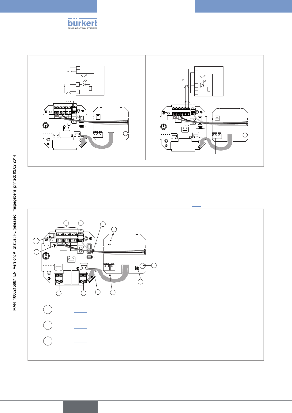
8.4.6. Wiring the 8025 compact version and the 8035, 115/230 V Ac, with
relays, with cable glands
→
Before wiring the device, configure the selectors on the electronic board (see chap. "8.3").
Supply
12..36Vdc
FLOW SENSOR
COIL
NPN
SOURCE SINK
L+
L-
PE
P-
P+
NC
L+
L-
PE
P-
P+
Iout
PULSE
OUTPUT
Without
With
Relays
N
PE
L
230V
T 125 mA
{
3
7
8
9
6
5
4
A
2
1
B
C
PE
Switch A : see chap. "8.3.1"
Switch B : see chap. "8.3.3"
Switch C : see chap. "8.3.2"
terminal block 1
lout: 4-20 mA output
L+ (red wire, factory wired)
L- (black wire, factory wired)
PE: wiring of the PE between the main board and the
protection board
P-: negative pulse output
P+: positive pulse output
terminal block 2 pe
Shield wiring (green/yellow wire, factory wired)
connector 3: connection of the flow sensor
terminal block 4: wiring of relay 1: see chap. "8.4.2"
terminal block 5: wiring of relay 2: see chap.
"8.4.2".
Jumper wire 6: jumper wire to be removed if the
4-20 mA output is connected
time-delay fuse 7: fuse to protect the 115 V AC or
230 V AC power supply
terminal 8: earth terminal, internally connected to
the earth plug
terminal block 9: wiring of the 115/230 V AC
power supply
Fig. 36: Terminal assignment of a 115/230 V AC compact version with relays, with cable glands
English