Wiring of the relays (versions with relay output), English, Power supply 4-20ma input at external instrument – Burkert Type 8025 User Manual
Page 32: 20ma input at external instrument power supply
32
Wiring
Type 8025 / 8035
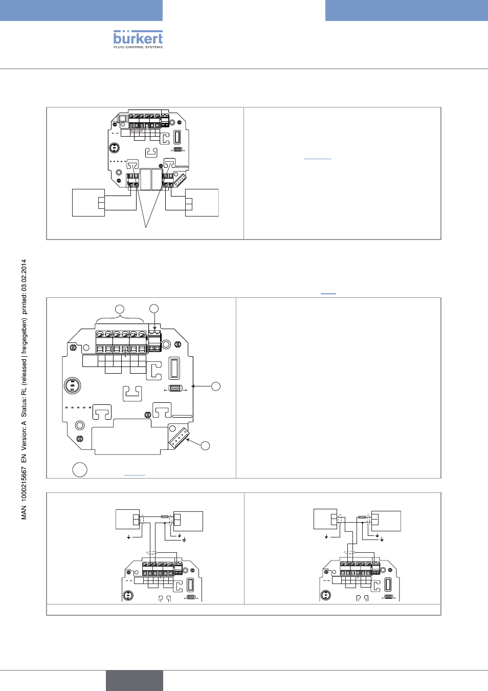
8.4.2. Wiring of the relays (versions with relay output)
Supply
12..36Vdc
FLOW SENSOR
COIL
NPN
SOURCE SINK
L+
L-
PE
P-
P+
NC
L+
L-
PE
P-
P+
Iout
PULSE
OUTPUT
Without
With
Relays
+
-
+
-
2
1
3
PE
Load 1
Load 2
• 1: relay 1 connection
• 2: relay 2 connection
• 3: fixation slots
→
Always secure the relays connection cables in the slots
marked 3 (see "Fig. 25").
Fig. 26: Wiring of the relays
8.4.3. Wiring the 8025 compact version and the 8035, 12-36 V Dc, without
relays, with cable glands
→
Before wiring the device, configure the selectors on the electronic board (see chap. "8.3").
Supply
12..36Vdc
FLOW SENSOR
COIL
NPN
L+
L-
PE
P-
P+
NC
L+
L-
PE
P-
P+
Iout
PULSE
OUTPUT
Without
With
Relays
PE
3
2
1
A
Switch A : see chap. "8.3.1"
terminal block 1
NC: not connected
L+: positive power supply
L-: negative power supply
PE: wiring of the PE between the main board and the protection
board
P-: negative pulse output
P+: positive pulse output
terminal block 2 pe
Wiring of the cable shields
connector 3: connection of the flow sensor
Fig. 27: Terminal assignment of a 12-36 V DC compact version without relays, with cable glands
Supply
12..36Vdc
FLOW SENSOR
COIL
NPN
SOURCE SINK
L+
L-
PE
P-
P+
NC
L+
L-
PE
P-
P+
Iout
PULSE
OUTPUT
Without
With
Relays
300 mA
+
-
12-36 V DC
+
-
(*)
PE
Power supply
4-20mA input at
external instrument
Supply
12..36Vdc
FLOW SENSOR
COIL
NPN
SOURCE SINK
L+
L-
PE
P-
P+
NC
L+
L-
PE
P-
P+
Iout
PULSE
OUTPUT
Without
With
Relays
300 mA
+
-
12-36 V DC
+
-
(*)
PE
4-20mA input at
external instrument
Power supply
(*) If direct earthing is not possible, insert a 100 nF / 50 V condensator between the negative terminal of the voltage supply and the earth.
Fig. 28: Possible wiring of the current output of a compact version, 12-36 V DC, without relays, with cable glands
English