Operation of an mfm or mfc sensor, Detailed operation of an mfc, Yx x – Burkert Type 8715 User Manual
Page 8
8
Descriptionofthesystem
Type 8700, 8701, 8703, 8705
5.1.2. General operation of the mass flow
controller (mfc)
The MFC comprises:
• a sensor for measuring the mass flow-rate,
• control electronics,
• an actuating element: low-friction solenoid control valve with a
high response sensitivity.
5.2.
operation of an mfm or mfc
sensor
• The integrated flow-rate sensors use the thermal measurement
process (anemometric and calorimetric) to measure the mass
flow-rate. The main components are a heating resistor and a
temperature probe. The gas which passes through the device
modifies the temperature difference measured between both
resistors.
• The thermal measurement principle allows the MFC to control the
required mass flow-rate completely independently of the pressure
and temperature fluctuations in the application concerned.
The damping of the output signal can be changed with the
"Mass Flow Communicator" (see chap. 10.1.3).
On the MFC types 8710, 8711, 8713, 8715, the
technology for the integrated sensor requires filters to be
fitted upstream of the product when highly soiled fluids are
present.
5.3.
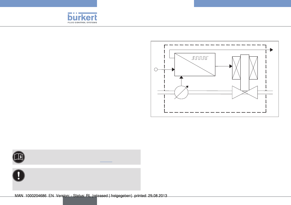
Detailed operation of an mfc
w
x
out
y
x
x
d
= w-x
Control
electronics
Sensor
Actuating element
(solenoid valve)
Gas
inlet
Gas
outlet
Fig. 1: Operating principle for the Mass Flow Controller
The control electronics compare the mass flow-rate (x) measured by
the integrated flow sensor with the mass flow-rate set-point value
(w) supplied to the MFC. The control electronics then calculate the
actuating variable (y) to be supplied to the solenoid valve to control
its opening. The flow-rate is either maintained at a constant value, or
modified to a predefined profile.
The control operates independently of fluctuations in pressure or
increases in the flow resistance which may be caused by soiling of the
filter. The rapidly responding solenoid valve and the sensor dynamics
define the overall responding time.
The measured value for the mass flow-rate is also transmitted (xout) to
a remote device via an analogue output or a digital output (field bus).
English