Pin assignment, Pin assignment 7.5.3 – Burkert Type 8709 User Manual
Page 31
31
Installation and Start-up
pin assignment
7.5.3.
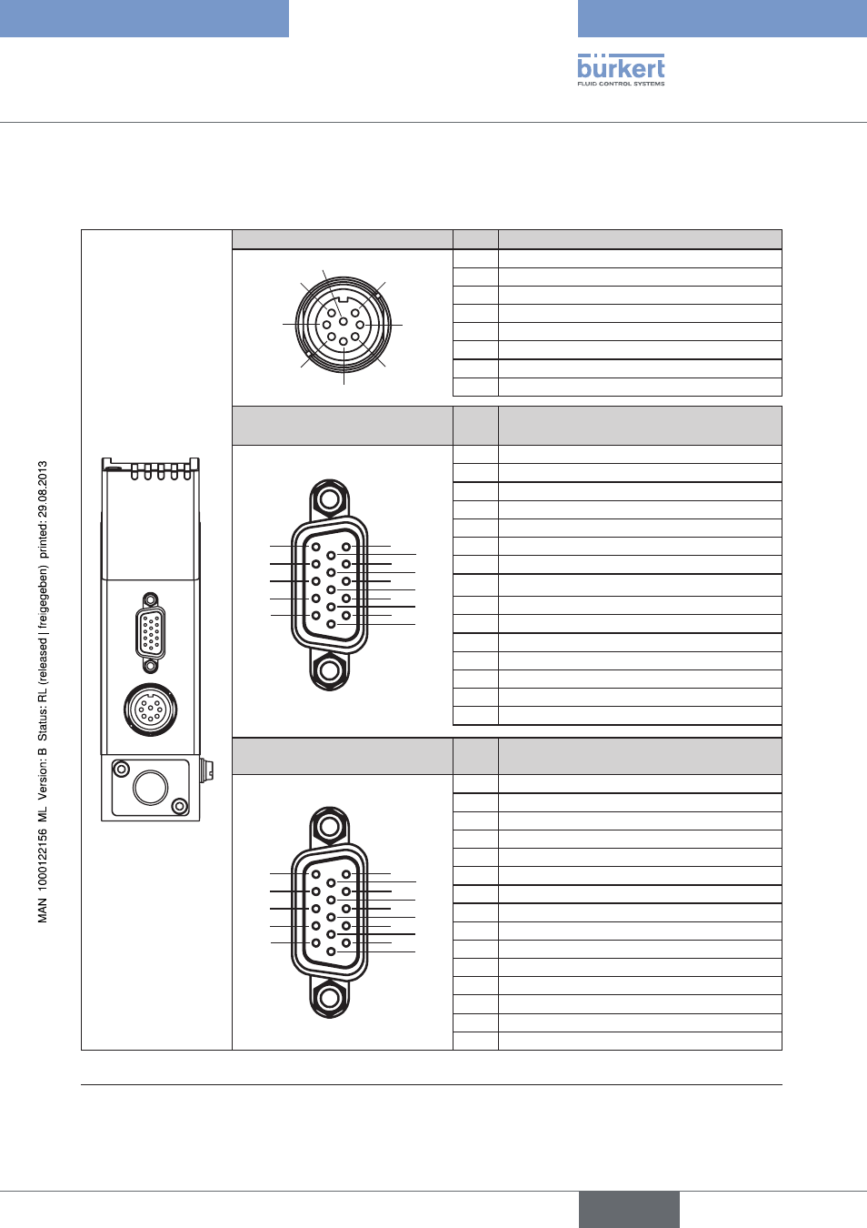
pin assignment lfc type 8719 and lfM type 8709
8-pole round socket
pin
configuration
1
4
2
3
5
6
7
8
1
24 V – supply +
2
Relay 1 – center contact
3
Relay 2 – center contact
4
Relay 1 – normally closed contact
5
Relay 1 – normally open contact
6
24 V – supply GND
7
Relay 2 – normally open contact
8
Relay 2 – normally closed contact
lfc type 8719:
socket suB-hd 15-pole
pin
configuration
10
9
8
7
6
1
4
3
2
5
15
14
13
12
11
1
1)
Set-point value input +
2
1)
Set-point value input GND
3
1)
Actual value output +
4
Binary input 2
5
12 V output (for internal use only)
6
RS232 T x D (direct connection to PC)
7
Binary input 1
8
DGND (for binary inputs)
9
for internal use only (do not use!)
10
12 V output (for internal use only)
11
12 V output (for internal use only)
12
Binary input 3
13
1)
Actual value output GND
14
RS232 R x D (direct connection to PC)
15
DGND (for RS232 interface)
lfM type 8709:
socket suB-hd 15-pole
pin
configuration
10
9
8
7
6
1
4
3
2
5
15
14
13
12
11
1
not used
2
not used
3
1)
Actual value output +
4
Binary input 2
5
12 V output (for internal use only)
6
RS232 T x D (direct connection to PC)
7
Binary input 1
8
DGND (for binary inputs)
9
for internal use only (do not use!)
10
12 V output (for internal use only)
11
12 V output (for internal use only)
12
Binary input 3
13
1)
Actual value output GND
14
RS232 R x D (direct connection to PC)
15
DGND (for RS232 interface)
Pin assignment LFC Type 8719 and LFM Type 8709
Table 1:
1)
In the field bus version the connections 1, 2, 3 and 13 are not used.
english
Type 8718, 8719 / 8708, 8709