Burkert Type 2002 User Manual
Page 5
WArnInG!
Risk of injury if the wrong tools are used!
• To remove the actuator from the valve body, use an open-end
wrench, never a pipe wrench.
• To replace the packing gland, use a special installation wrench
(see Internet at:
www.burkert.com
→ Type 2000 → Maintenance
EU ML, section Installation wrench).
• Observe tightening torques!
Before the packing gland can be replaced, the actuator must be
removed from the valve body and the swivel plate removed.
→
Clamp the valve body
1
into a holding device (applies only to
valves not yet installed).
note!
Damage to the seat contour!
• When removing the actuator, ensure that the valve is in the open
position.
→
For control function A: pressurize the lower control air connection
with compressed air (5 bar): Valve opens.
→
Place a suitable open-end wrench on the wrench flat of the
nipple
6
.
→
Unscrew actuator on the valve body
1
.
→
Remove compressed air from the control air connection.
→
Knock out pin
4
on swivel plate
3
with a suitable pin punch:
pin punch ø 3 mm for spindle diameter 10 mm and
pin punch ø 5 mm for spindle diameter 14 mm.
→
Remove swivel plate
3
.
→
Unscrew spindle guide
7
with the help of the installation tool
and an open-end wrench.
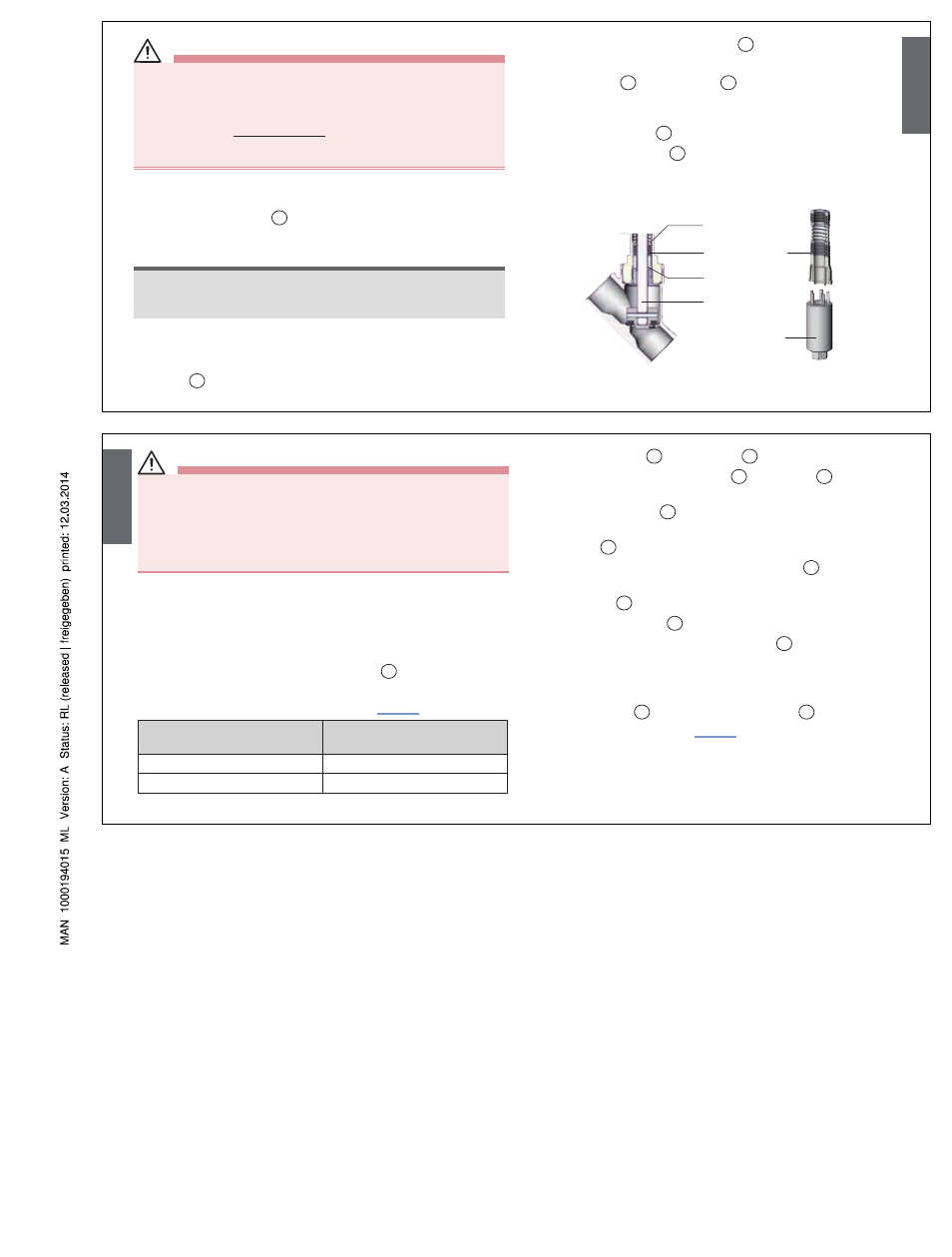
Installation wrench
Packing gland
Spindle guide
Spindle
Packing gland tube
English
WArnInG!
Risk of injury from ejected parts!
When the spindle opening is exposed, the individual parts of the
packing gland are pressed out at an undefined speed when the control
air connection is pressurized.
• Before pressurizing with control air, safeguard the ambient area of
the discharge opening (e.g. place spindle on a firm base).
→
Pressurize the lower control air connection with 6 bar – 8 bar.
→
Grease the individual parts of the new packing gland with the
supplied lubricant.
→
Place the individual parts on the spindle in the prescribed
direction and sequence.
→
Push packing gland packing into the tube
8
.
→
Screw in spindle guide again before using the installation wrench.
Observe tightening torques according to “Tab. 2”!
Spindle diameter
(mm)
Tightening torques
(Nm)
10
6
14
15
Tab. 2: Spindle guide tightening torques
→
Place swivel plate
3
on the spindle
2
.
→
Align drill holes of the swivel plate
3
and spindle
2
so that they
are flush with one another.
→
Support swivel plate
3
on the cylindrical part with the help of a
prism.
→
Insert pin
4
into the drill hole.
→
Calk pin bores on both sides of the swivel plate
3
with chisel or
prick punch.
→
Clamp body
1
.
→
Replace graphite seal
5
.
→
Only for VA body: Lubricate nipple thread
6
with Klüber paste
UH1 96-402.
→
For control function A (CFA): Pressurize lower control air con-
nection with compressed air (5 bar).
→
Screw in nipple
6
with actuator in valve body
1
. Observe tight-
ening torques according to “Tab. 1”.
English