Burkert Type 2002 User Manual
Page 4
For actuator size D (50 mm) the tube
8
is screwed and
sealed in the nipple
6
.
→
Release and remove screw
18
with socket spanner.
→
Remove disk springs
17
.
→
Remove actuator body
12
.
→
Only actuator size C (40 mm): Replace O-ring
11
.
→
Replace O-ring
36
.
Reinforcing ring
10
remains on the tube
8
.
→
Slide packing gland set
7
,
13
,
14
,
15
,
16
carefully out of the
tube
8
. Take care that the tube is not damaged.
→
Clean all replacement parts thoroughly after removal.
aSSembly
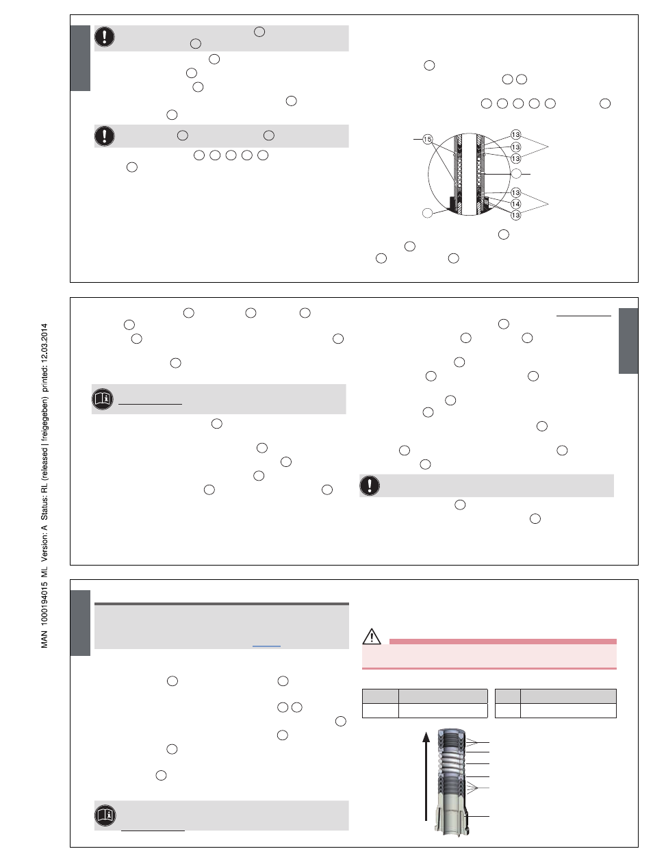
Rebuild packing gland set based according to the drawing:
→
Lubricate new wiper with silicone grease OKS 1110-3 and insert
into the tube
8
.
→
Lubricate individually chevron seal
13
14
liberally with silicone
grease OKS 1110-3.
→
Assemble packing gland set
7
,
13
,
14
,
15
,
16
in the tube
8
in the right sequence (see detailed drawing).
Chevron seal
Pressure
rings
Chevron seal
16
Pressure spring
7
→
Push packing gland into the tube
8
as far as the stop; clamp
nipples
6
to do this and screw in packing gland set with screw
18
. Remove screw
18
again.
English
→
Mount actuator body
12
, disk springs
17
and screw
18
on the
tube
8
.
→
Screw
18
with socket spanner; ensuring that the disk springs
17
are in a central position.
→
Lubricate spindle
2
lightly with silicone grease OKS 1110-3
and insert suitable assembly sleeve over spindle thread.
For information about the assembly sleeve, see:
www.burkert.com
→ Type 2000 → Maintenance-EU-ML,
section Installation Wrench.
→
Insert spindle through nipple
6
into actuator and remove
assembly sleeve.
→
For control function A: Place filler piece
19
on spindle.
→
For control function B: Insert pressure springs
35
.
→
For control function I: Insert filler piece
19
.
→
Place intermediate washer
20
and lightly lubricated O-ring
21
on
spindle.
The following operations must only be carried out with all valves:
→
Lubricate mounting actuator body
12
; lubricant Amblygon TA.
→
Remove old piston seal
23
from pistons
22
, clean groove and
lubricate well; lubricant Amblygon TA.
→
Insert new piston ring
23
.
→
Insert pistons
22
and supporting washer
24
and lightly lubricate
bearing surface.
→
Wet spindle thread
2
with special adhesive LOCTITE 274 and
screw on nut
25
.
→
Carefully screw in actuator on the swivel plate
3
(only put pressure
on the upper section of the swivel plate).
→
Screw
25
nut tightly and mount position indicator
26
.
→
Clamp body
1
.
Do not damage sealing edges when replacing the seal!
→
Replace graphite seal
5
.
→
Only for VA body: Lubricate nipple thread
6
with Klüber paste
UH1 96-402.
English
note!
Damage to the seat contour!
• During installation, take care that there is no damage to the seat
contour.
• Observe tightening torques according to “Tab. 1”.
→
For control function A (CFA): Pressurize lower control air con-
nection with compressed air (5 bar).
→
Screw in nipple
6
with actuator in valve body
1
.
→
Only for type 2002: Use sealing tape.
→
For control function A: Use pressure springs
28
29
.
→
Only actuator size G (100 mm) and H (125 mm): Insert washer
40
.
→
For control function B and I: Change O-ring
30
.
→
Replace O-ring
32
; to do this, remove transparent cap.
→
Lightly lubricate cover thread, lubricant Amblygon TA.
→
Mount cover
31
and screw tightly with special wrench.
→
Check the valve for function and leaks.
A detailed description about how to change spare parts and
maintenance of valves can be found at:
www.burkert.com
→ Type 2000 → Maintenance-EU-ML.
CHaNGe THe paCkING GlaND FoR ValVeS
WITH aCTUaToR SIze F (80 mm), G (100 mm),
H (125 mm) aND IDeNTIFICaTIoN "R"
DAnGer!
Risk of injury from discharge of medium and release of pressure!
• Before removing a device, switch off the pressure and vent the lines!
The seal set for the packing gland contains:
Item
Description
Item
Description
13, 14
7 chevron seal
7
1 spindle guide
Upper chevron seal
Upper pressure ring
Pressure spring
Lower pressure ring
Lower chevron seal
Spindle guide
Pushing direction
for packing gland parts
English