Burkert Type 2002 User Manual
Page 3
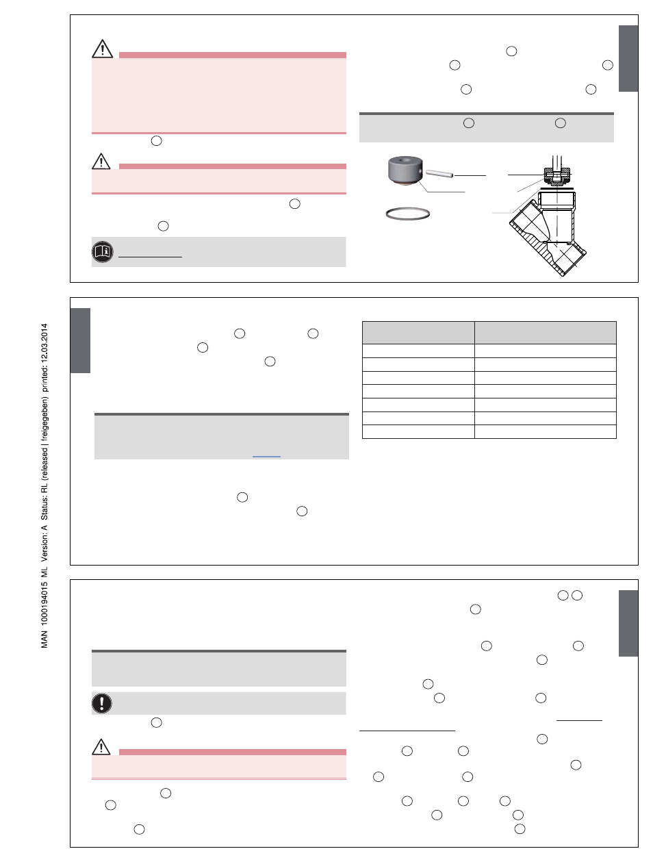
ReplaCING THe ValVe SeT
DAnGer!
Danger – high pressure!
• Turn off the pressure and vent the lines before loosening lines or
valves.
Risk of injury from improper maintenance!
• Maintenance may be performed by authorized technicians only!
• To screw on or unscrew valve body or actuator, use an open-end
wrench, never a pipe wrench, and observe tightening torques.
→
Mount valve
1
on the body.
CAutIon!
Danger through taut springs!
• Carefully open piston actuator!
→
Only for control function A (CFA): Release cover
31
with special
wrench until the springs are completely relaxed, holding up the
actuator body
12
against the hexagon.
For information about the special wrench, see:
www.burkert.com
→ Type 2000 → Maintenance-EU-ML,
section Installation wrench.
→
For control function A (CFA): Pressurize lower control air con-
nection with compressed air (5 bar).
→
Unscrew actuator on the valve body
1
.
→
Support swivel plate
3
with the help of a prism, knock out pin
4
with a pin punch and pull out swivel plate.
→
Mount new swivel plate
3
align and secure with new pin
4
.
note!
For valves with "R" sleeves
3*
, insert in swivel plate
3
and align
drilled holes.
Pin
Swivel plate
Graphite seal
English
→
Calk pin bores on both sides of the swivel plate with chisel or prick
punch.
→
Carefully remove old graphite seal
5
from valve body
1
.
→
Insert new graphite seal
5
.
→
Only for VA body: Lubricate nipple thread
6
with Klüber paste
UH1 96-402.
→
Only for type 2002: Use sealing tape.
note!
Damage to the seat contour!
• During installation, take care that there is no damage to the seat
contour.
• Observe tightening torques according to “Tab. 1”.
→
For control function A (CFA): Pressurize lower control air con-
nection with compressed air (5 bar).
→
Screw in valve actuator with nipple
6
into the body.
→
Only for control function A (CFA): Rescrew cover
31
with
special wrench.
→
Check the valve for function and leaks.
Tightening torques
DN
(mm)
Tightening torques
(Nm)
15
45
20
50
25
60
32
65
40
65
50
70
65
70
Tab. 1: Valve body tightening torques
English
CHaNGING THe Seal SeT
Change seal set with actuator with control function A (locked by
spring force in the rest position), control function B (opened by spring
force in the rest position) and control function I (dual acting)
note!
The actuator must be completely removed to replace all the seals.
A special Bürkert assembly sleeve is required to mount the packing
gland.
Do not use any pointed or sharp instruments!
→
Mount valve
1
on the body.
CAutIon!
Danger through taut springs!
• Carefully open piston actuator!
→
Unscrew cover
31
with special wrench holding up the actuator body
12
against the hexagon.
→
Only for actuator size G (100 mm) and H (125 mm): Remove
washer
40
.
→
For control function A: Remove pressure springs
28
29
.
→
Remove position indicator
26
with Allen key.
→
For control function A (CFA): Pressurize lower control air con-
nection with compressed air (5 bar).
→
Screw actuator on the nipple
6
out of the valve body
1
.
→
Carefully screw in actuator on the swivel plate
3
(only put pressure
on the upper section of the swivel plate).
→
Release nuts
25
.
→
Remove pistons
22
with supporting washer
24
.
The following operations must only be carried out with valves
without identification "R":
→
For control function A: Remove filler piece
19
with intermediate
washer
20
and O-ring
21
.
→
For control function B: Remove intermediate washer
20
, O-ring
21
and pressure spring
35
.
→
For control function I: Remove filler piece with intermediate
washer
20
and O-ring
21
(spring
35
missing).
→
Remove spindle
2
from actuator body
12
and clean spindle thread.
→
Clamp actuator on the nipple hexagon
6
.
English