Draw-Tite 118459 T-ONE CONNECTOR User Manual
Draw-Tite For the car
6. Disconnect and isolate the vehicle’s
Negative (-) battery terminal.
CAUTION
Read and follow all warnings and cautions
printed on the tow vehicle’s battery.
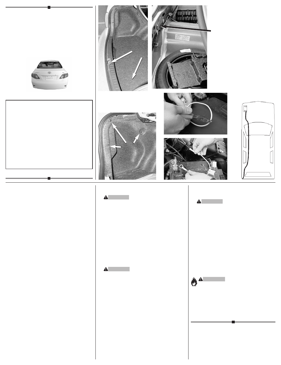
If not removed, remove the fuse from
the yellow fuse holder (provided). After
cutting the fuse holder wire, attach the
ring terminal and secure to the vehicle’s
Positive (+) battery cable
g
. Connect the
other end of the fuse holder to the black
12 ga. wire, using the yellow butt
connector (provided)
h.
7. Route the black wire out of the engine
compartment either along the exterior
frame and thru a grommet or thru the
interior following the existing wiring to
the rear of the vehicle.
i
WARNING
Route the wire being careful to avoid any
hot pipes, heat shields, the fuel tank or
any other points that may pinch or break
the wire.
From inside the trunk, connect
the black 12 ga. wire and the red wire
from the T-Connector black box with the
supplied yellow butt connector.
118459-037
Rev. A
01/24/08
ENGLISH
TOOLS REQUIRED:
Trim Panel Remover, 10mm Socket &
Ratchet or 10mm Wrench
Drill (3/32” Drill Bit), 1/4” socket
Wire Crimpers, Wire Cutters
Philips Head Screwdriver, Test-probe
1. Open trunk and remove threshold panel
and floor coverings. Partially remove
the corner felt trunk liner, on both sides,
exposing the vehicle’s taillight wiring
harness.
d e
2. Behind the taillights, there will be
connection points matching the ends
of the T-Connector adapter on the back
of each of the vehicle taillight housings.
3. Beginning on the driver’s side, separate
the vehicle’s wiring connectors, being
careful not to break the locking tabs.
Plug the T-Connector harness containing
the yellow wire in between the vehicle’s
mating connectors. All connector surfaces
should be clean and free of dirt.
4. Route the T-Connector end with green
wire to the passenger ‘s side behind the
panels and along the threshold. Repeat
step 3 for T-Connector end with the green
wire.
f
5. Locate existing ground stud. Loosen the
nut, place T-Connector white wire with
ring terminal on stud and retighten the
nut, making sure that all existing ground
connections are still attached.
•
d
•
e
•
f
READ THIS FIRST:
Read and follow all vehicle warnings and
installation instructions before beginning
installation. Wear safety glasses and use
all safety precautions during installation.
LISEZ CECI EN PREMIER:
Lire et observer toutes les consignes de sécurité
et les instructions avant de commencer l’installa-
tion. Durant l’installation, veiller à toujours porter
des lunettes de protection et respecter les
mesures de sécurité.
LEA ESTO PRIMERO:
Lea y siga todas las advertencias e instrucciones
de instalación del vehículo antes de empezar la
instalación. Use gafas de seguridad y todas las
precauciones de seguridad durante la instalación.
Installation Instructions
Directives de Montage
Instrucciones de Instalación
T-Connector
Connecteur en T
Conector en T
Toyota Corolla
8. Reconnect the vehicle’s Negative (-)
battery cable and install the 10 amp
fuse into the fuse holder from step 6.
WARNING
All connections must be complete for the
T-Connector to function properly. Test and
verify installation with a test light or trailer
once installed. For initial test, reset vehi-
cle electrical system by temporarily
removing the key from the ignition.
9. On driver’s side, locate a flat surface in
a out of the way place and mount the
T-Connector’s black convertor box with
the double sided tape.
10. Replace the trunk threshold panel, floor
coverings and felt trunk liner removed
during installation.
NOTE
Store 4-Flat in trunk area when not in
use.
WARNING
Overloading circuit can cause fires. DO
NOT exceed lower of towing
manufacturer rating or:
• Max. stop/turn light: 1 per side
(2.1 amps)
• Max. tail lights: (4.2 amps)
Read vehicle’s owners manual &
instruction sheet for additional
information.
Remove
Retirer
Retire
Remove
Retirer
Retire
Ground Stud
Borne de masse
Termianl a tierra
•
i
•
g
•
h