Draw-Tite 118449 T-ONE CONNECTOR User Manual
Draw-Tite For the car
118449-037
Rev. A
09/26/07
ENGLISH
TOOLS NEEDED:
Test-probe, Trim Panel Remover
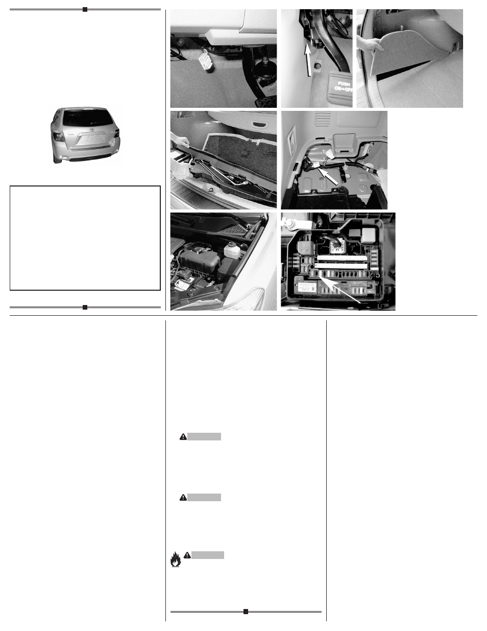
1. Locate the vehicle’s 10-Pin tow plug located
underneath the dash on the driver’s side
between the emergency brake pedal and the
brake pedal
d. Check to see that the mating
surfaces of the vehicle harness connectors
match the 10-Pin tow plug adapter ends.
2. Insert the 10-Pin tow plug adapter and lock into
place. Be careful not to damage the locking tabs
and be sure that connectors are fully inserted
with locking tabs in place.
3. Route the convertor over to the driver’s
side kick panel area. Locate the opening
between vehicle body and emergency brake
pedal bracket
e. Mount the black box in this
area using the double-sided tape provided.
To prevent damage or rattling, be careful to
avoid any areas that would cut or pinch the
wire. Using cable ties provided, secure the
remainder of the wire harness to prevent from
having wires exposed underneath the dash area.
4. Open the vehicle’s rear tailgate. On the driver’s
side, remove access panels, threshold, trunk
floor panels and trays
f g. Set aside all items
removed being careful not to damage parts.
5. On the driver’s side, locate the vehicle’s factory
4-Pin tow harness connector
h. Check to see
that the mating surfaces of the vehicle harness
connectors match the Tow-Plug Adapter end.
All connector surfaces should be clean and
free of dirt.
6. Insert the 4-Pin Tow-Plug Adapter and lock into
place. Be careful not to damage the locking tabs
and be sure that connectors are fully inserted
with locking tabs in place.
7. Reposition the trays, trunk floor panels and
access panels and reattach the threshold.
NOTE
Store 4-Flat in trunk or rear cargo area when
not in use.
8. Open the hood and locate the vehicle fuse panel
on the Driver’s side
i. Consulting your owner’s
manual, locate the Towing Fuse location and
insert the 10A fuse (provided)
j.
WARNING
Do not replace with any fuse that exceeds
10 amps.
NOTE
Additional 10 amp fuse located on the wiring
harness underneath the dash between the
10-pin tow plug and the black box.
WARNING
All connections must be complete for the
T-Connector to function properly. Test and
verify installation with a test light or trailer
once installed. For initial test, reset vehicle
electrical system by temporarily removing
the key from the ignition.
WARNING
Overloading circuit can cause fires. DO NOT
exceed lower of towing manufacturer rating or:
• Max. stop/turn light: 1 per side (2.1 amps)
• Max. tail lights: (5.6 amps)
Read vehicle’s owners manual & instruction
sheet for additional information.
•
f
•
g
•
d
•
e
Installation Instructions
Directives de Montage
Instrucciones de Instalación
T-Connector
Connecteur en T
Conector en T
READ THIS FIRST:
Read and follow all vehicle warnings and installation instructions
before beginning installation. Wear safety glasses and use all
safety precautions during installation.
LISEZ CECI EN PREMIER:
Lire et observer toutes les consignes de sécurité et les instruc-
tions avant de commencer l’installation. Durant l’installation,
veiller à toujours porter des lunettes de protection et respecter
les mesures de sécurité.
LEA ESTO PRIMERO:
Lea y siga todas las advertencias e instrucciones de instalación
del vehículo antes de empezar la instalación. Use gafas de
seguridad y todas las precauciones de seguridad durante
la instalación.
•
h
•
i
•
j
Toyota Highlander