Draw-Tite 118525 T-ONE CONNECTOR User Manual
Fd e
118525-037
Rev. A
02/24/11
ENGLISH
Tools Needed:
Test-probe, Trim Panel Puller
JUMPeR HARNess INsTAllATIoN
1. Insert relays. (Included)
NoTe
The use of relays that differ from the relays
included can result in the unit not to function
or may damage the vehicle and or trailer.
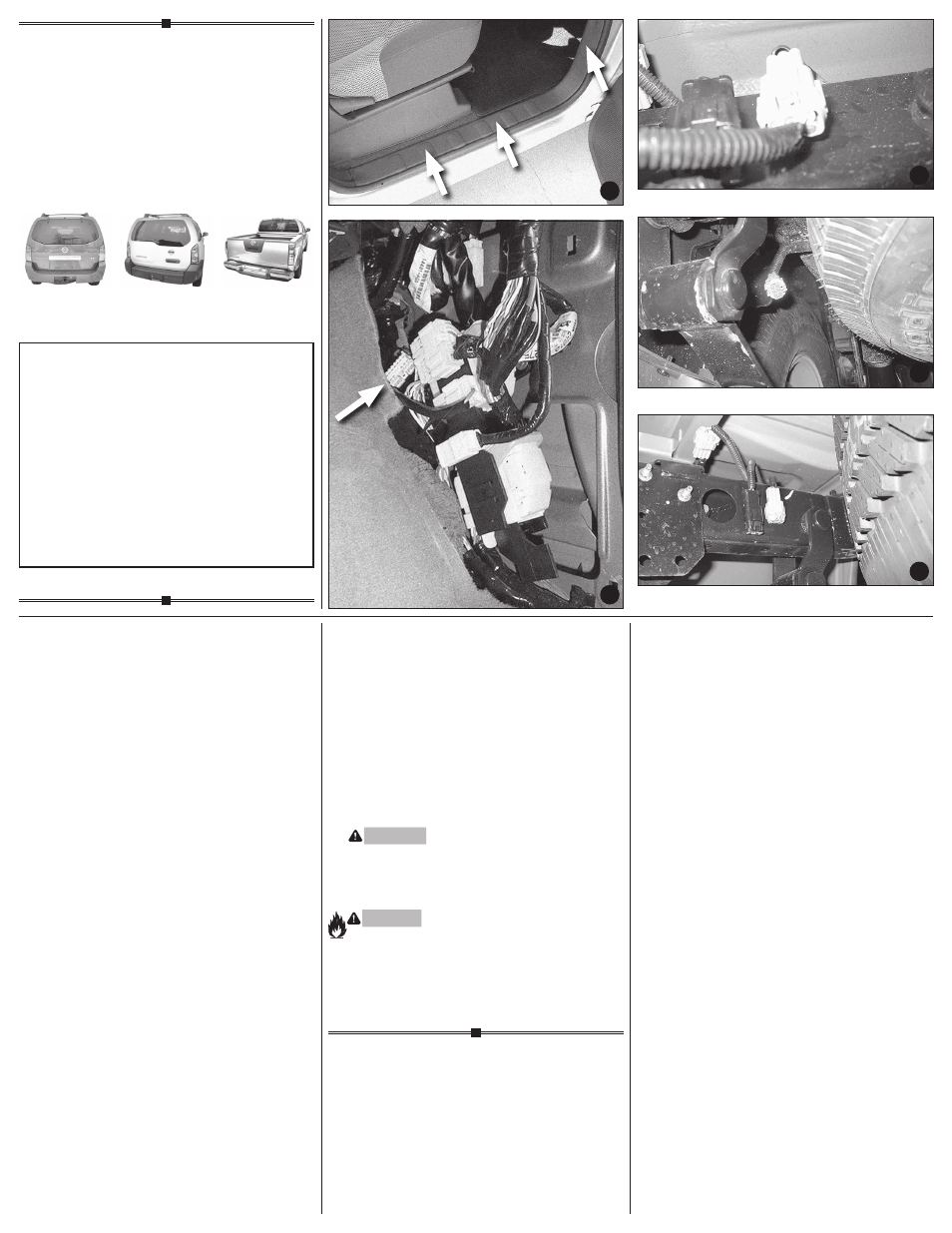
2. Start by locating the vehicle’s 12 pin jumper plug
located in vehicle cab on the passenger’s side,
behind the kick panel.
3. Using a trim panel puller, temporarily remove
passenger side floor sill by first pulling upwards
(1) and then out towards the rear of the vehicle
(2), being careful not to damage the panel
fasteners
d
.
Remove the passenger side kick panel. The 12 pin
jumper plug will be located behind this panel and
will mate with the included jumper plug
e
.
4. Insert the jumper harness with relays the vehicle’s
12 pin harness and lock into place. Ensure that the
connectors are fully inserted with locking tabs in
place. Secure the remainder of the jumper harness
with the cable ties and foam tape provided, to
prevent damage or rattling and being careful to
avoid any areas that would cut or pinch the wire.
5. Replace the passenger side kick panel and floor
sill into their original positions.
ToW PlUG HARNess INsTAllATIoN
1. Locate the tow vehicle’s trailer harness
connector. The gray 6-pin plug is located
under the vehicle, behind the rear bumper
on the driver’s side, along the frame rail
f
.
2. Remove the protective cap from connector.
All connector surfaces should be clean and
free of dirt.
3. Connect the T-Connector end to the vehicle’s
mating connector. Be careful not to damage
the locking tabs and be sure that connectors
are fully inserted with locking tabs in place.
WARNING
All connections must be complete for the
T-Connector to function properly. Test and
verify installation with a test light or trailer
once installed.
WARNING
Overloading circuit can cause fires. DO NOT
exceed lower of towing manufacturer rating or:
• Max. stop/turn light: 1 per side (7.5 amps)
• Max. tail lights: (7.5 amps)
Read vehicle’s owners manual & instruction sheet
for additional information.
ReAd THIs FIRsT:
Read and follow all vehicle warnings and installation
instructions before beginning installation. Wear safety
glasses and use all safety precautions during installation.
lIsez CeCI eN PReMIeR:
Lire et observer toutes les consignes de sécurité et les
instructions avant de commencer l’installation. Durant
l’installation, veiller à toujours porter des lunettes de
protection et respecter les mesures de sécurité.
leA esTo PRIMeRo:
Lea y siga todas las advertencias e instrucciones de
instalación del vehículo antes de empezar la instalación.
Use gafas de seguridad y todas las precauciones de
seguridad durante la instalación.
Installation Instructions
directives de Montage
Instrucciones de Instalación
T-Connector
Connecteur en T
Conector en T
Pathfinder
Xterra
Frontier/
equator
Pathfinder
f
Frontier / equator
f
Xterra
f
d
e