Draw-Tite 118415 T-ONE CONNECTOR User Manual
Draw-Tite For the car
6. Locate a suitab
le grounding point near the
connector such as the vehicle's frame or cross
member
k
.
(Do not drill into vehicle floor or
bed.) Clean dirt and rustproofing from area.
Drill a 3/32" hole and secure
white wire using
eyelet and screw provided.
CA
UTION
V
erify what is behind any surface prior to
drilling to avoid damage to the vehicle and/
or personal injury. Do not drill into any
exposed surfaces.
W
ARNING
All connections m
ust be complete for the
T-Connector to function properly. Test and
verify installation with a test light or trailer
once installed.
7. Mount the
T-connector
b
lack
bo
x using
double-sided tape provided
k
.
Secure the
remainder of the T-connector harness with
the cable ties provided. To prevent damage
or rattling, be careful to avoid any areas
that would cut or pinch the wire.
8. Reposition the access panels
, trays and trunk
floor panels and reattach the threshold.
NO
TE
Store 4-Flat in tr
unk or rear cargo area when
not in use.
W
ARNING
Ov
erloading circuit can cause fires. DO NOT
exceed lower of towing manufacturer rating or:
• Max. stop/turn light: 1 per side (2.1 amps)
• Max. tail lights: (5.0 amps)
Read vehicle's owners manual & instruction
sheet for additional information.
ENGLISH
TOOLS NEEDED
10mm Soc
ket & Ratchet or 10 mm Wrench,
Drill, Phillips Head Screwdriver, Test Probe
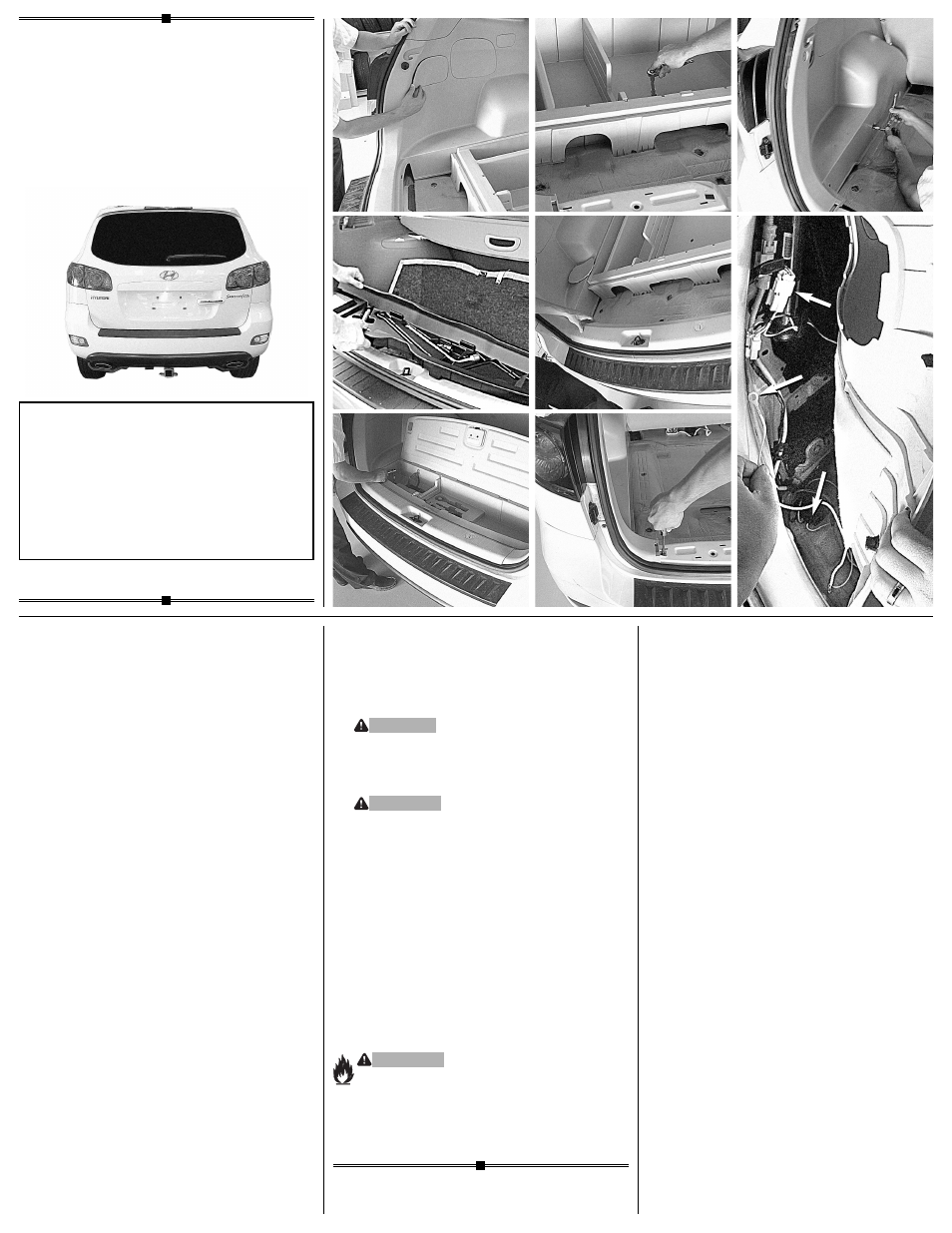
1. Open the v
ehicle’s rear tailgate. On the
driver’s side remove access panel to locate
rear of taillight
d
.
Repeat on the passenger
side. Remove threshold, trunk floor panels and
trays
e
f g h
.
Set aside all items removed
being careful not to damage parts.
2. Remo
ve two screws in the threshold plate
area
i
, to gain access behind tr
im panels.
Being careful not to damage clips, partially
remove the lower interior trim panels on each
side of the vehicle
j
.
Set aside all items
removed being careful not to damage parts.
3. On the dr
iver and passenger sides of the
vehicle, locate the vehicle's taillight wiring
harness
k
.
The taillight wiring harness will
have a connection point, on both sides,
matching the ends of the T-Connector.
Separate these connectors, being careful
not to break the locking tabs. All connector
surfaces should be clean and free of dirt .
4. On the dr
iver’s side insert the T-Connector
end, with the
y
ellow
wire
, between the vehicle
wiring connectors and lock into place. Be sure
that connectors are fully inserted with locking
tabs in place.
5. Route the
T-Connector end with
green wire
to the passenger's side. Repeat step 4 on
the passenger's side with T-connector end
containing the
green wire
.
118415-037
Rev. A
06/27/06
Installation Instr
uctions
Directives de Montage
Instrucciones de Instalación
T-Connector
Connecteur en T
Conector en T
READ
THIS FIRST:
Read and f
ollow all instructions carefully
before beginning installation.
LISEZ CECI EN PREMIER:
Lire et suivre toutes les instr
uctions
attenrivement avant le montage.
LEA
ESTO PRIMERO:
Lea y siga todas las instr
ucciones cuidadosa-
mente antes de iniciar la instalación.
•
f
•
i
•
e
•
g
•
j
•
h
•
d
•
k