Draw-Tite 118519 T-ONE CONNECTOR User Manual
Draw-Tite For the car
READ THIS FIRST:
Read and follow all vehicle warnings and
installation instructions before beginning installation.
Wear safety glasses and use all safety precautions
during installation.
LISEz CECI En PREmIER:
Lire et observer toutes les consignes de sécurité et les
instructions avant de commencer l’installation. Durant
l’installation, veiller à toujours porter des lunettes
de protection et respecter les mesures de sécurité.
LEA ESTO PRImERO:
Lea y siga todas las advertencias e instrucciones
de instalación del vehículo antes de empezar la
instalación. Use gafas de seguridad y todas las
precauciones de seguridad durante la instalación.
118519
Rev. A
12/06/10
Installation Instructions
Directives de montage
Instrucciones de Instalación
T-Connector
Connecteur en T
Conector en T
ENGLISH
TOOLS REQUIRED:
10mm Socket & Ratchet or 10mm Wrench, Drill
(3/32” Drill Bit), Test-probe
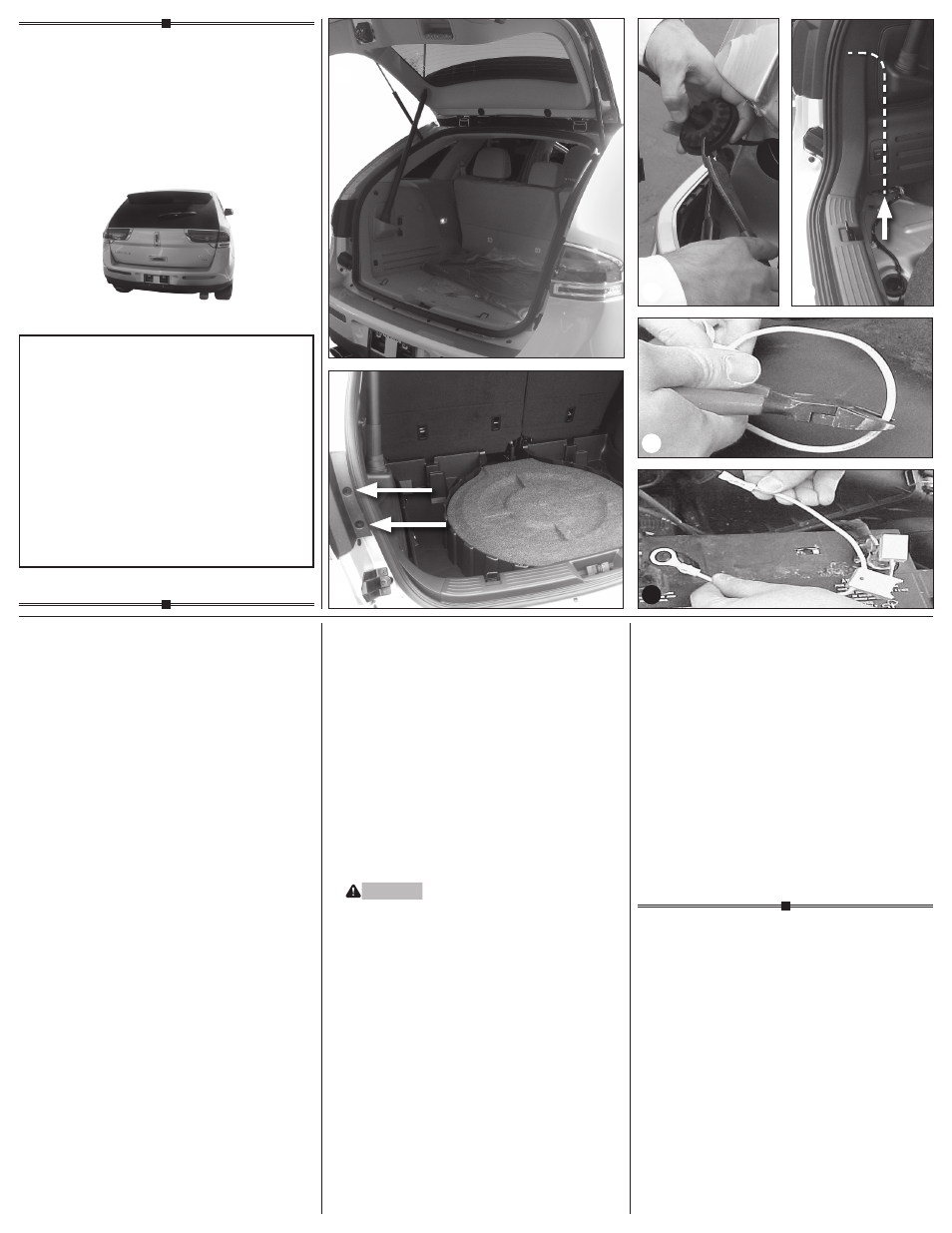
1. Open the vehicle’s rear tailgate, remove cargo
nets and cargo floor hatch to access the spare tire
area
d
. Remove both taillight housing assemblies
by removing the two bolts for each light and care-
fully prying the vehicle taillight housing assembly
away from the vehicle, being careful not to break
the alignment tabs
e
.
2. Disconnect the wiring harness at the plugs located
in the taillight pocket.
3. On both the driver’s and passenger’s side, slit the
grommet to allow for T-Connector’s wiring
f
.
Route the wire inside vehicle through each interior
trim panel and route the T-Connector containing
the green wire down the threshold plate, up and
through the passenger side trim panel and out
through the grommet hole
g
.
4. Plug the T-Connector end with the yellow wire
in-between the mating plugs on the Driver’s side
taillight socket and vehicle wiring harness.
5. Repeat step 4 for the passenger’s side using
the T-Connector containing the green wire.
6. Locate a suitable grounding point near the
connector such as an existing ground stud or drill
a 3/32” hole and secure the white wire using the
eyelet and screw provided. (Do not drill into vehicle
floor or bed.) Clean dirt and rustproofing from area.
7. Locate the T-Connector’s Grey 12-Pin connector
and insert it into the mating connector located on
the black box-module. Check to see that the mating
surfaces of the wiring connectors match. All con-
nector surfaces should be clean and free of dirt. Be
careful not to damage the locking tabs and be sure
that connectors are fully inserted with locking tabs
in place.
8. Locate a flat surface in an out of the way place and
mount the T-Connector’s black box-module, to
prevent damage or rattling.
nOTE
This surface should be in an area that is free of
any moisture and mounted in an area that it is high
enough where it could not be exposed to direct
contact with any water or liquid substance.
WARnInG
The black box-module is intended to be mounted
ONLY in the INTERIOR of the vehicle. Mounting on
the exterior or areas exposed to the elements or
moisture could cause serious damage to the vehicle
and module.
Secure the remainder of the T-Connector harness
with the cable ties provided, to prevent damage or
rattling and being careful to avoid any areas that
would pinch, cut or melt the wire.
9. Beginning from the front of the vehicle, route the
black 12 ga. wire rearward along the frame rail
avoiding any hot pipes, heat shields, the fuel tank or
any other points that may pinch or break the wire.
10. On the driver’s side, locate the Red 12 ga. Power
wire from the T-Connector box. Connect the black
12 ga. Wire and the two black wires from the
T-Connector’s grey 12-Pin connector with the
supplied yellow butt connector. Disconnect and
isolate the vehicle’s negative battery terminal. If not
removed, remove the fuse from the supplied fuse
holder. After cutting the fuse holder wire
h
, attach
the ring terminal and secure to the vehicle’s Posi-
tive (+) battery cable. Connect the other end of the
fuse holder to the black 12 ga. wire included, using
the supplied Yellow butt connector.
11. Beginning from the front of the vehicle, route the
black 12 ga. wire rearward along the frame rail
avoiding any hot pipes, heat shields, the fuel tank
or any other points that may pinch or break the
wire
i
.
Lincoln mKX
e
f
g
h
i
d