Draw-Tite 118546 T-ONE CONNECTOR User Manual
English
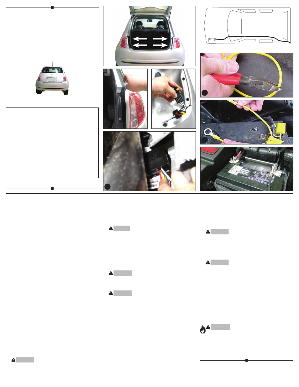
9. Disconnect the vehicle’s Negative (-) battery cable.
If not removed, remove the fuse from the yellow fuse
holder (provided). After cutting the fuse holder wire,
attach the ring terminal and secure to the vehicle’s
Positive (+) battery cable i. Connect the other end
of the fuse holder to the black 12 ga. wire, using the
yellow butt connector (provided) jk.
WARNING
Read and follow all warnings and cautions printed
on the tow vehicle’s battery.
10. Reconnect the vehicle’s Negative (-) battery cable
and install the 10 amp fuse into the fuse holder
from step 9.
WARNING
All connections must be complete for the T-Connector
to function properly. Test and verify installation with a
test light or trailer once installed. For initial test, reset
vehicle electrical system by temporarily removing the
key from the ignition.
11. Secure the remainder of the T-Connector harness
with the cable ties provided, to prevent damage or
rattling and being careful to avoid any areas that
would pinch, cut or melt the wire.
12. Reinstall taillight assemblies and other items removed
during installation, being careful not to pinch or cut
the wires.
WARNING
Overloading circuit can cause fires. DO NOT exceed
lower of vehicle manufacturer rating or:
• Max. stop/turn light: 2 per side (4.2 amps)
• Max. tail lights: (7.5 amps)
Read vehicle’s owners manual & instruction sheet for
additional information.
118544-037
Rev. A
05/27/11
ENGLISH
TOOLS NEEDED:
Trim Panel Remover, 10mm Socket & Ratchet
or 10mm Wrench, Drill (3/32” Drill Bit),
1/4” Socket, Wire Crimpers, Wire Cutters,
Philips Head Screwdriver, Test-probe
1. Open the rear tailgate to access the bolts that
hold the taillights in place. Using a Phillips head
screwdriver, Remove the taillights on both the driver
and passenger side of the vehicle. After removing
the screws, carefully pull the taillight away from
the vehicle being careful not to damage the
alignment pins de.
2. On the Driver’s side, disconnect the vehicle
wiring harness from the taillight socket.
Separate this connector, being careful not to
break the locking tabs. All connector surfaces
should be clean and free of dirt f.
3. On the driver’s side, insert the T-Connector end,
with the yellow wire, between the vehicle wiring
connectors and lock into place. Be careful not to
damage the locking tabs and be sure that connectors
are fully inserted with locking tabs in place.
4. Begining at the Driver’s side taillight pocket, route
the harness containing the green wire and the 4-Flat
down the opening between the vehicle bumper and
body. Then route the harness and 4-Flat across and
underneath the vehicle behind the bumper fascia.
Route 4-Flat to the center of the vehicle. Secure wire
cable ties provided. Continue to route the harness
containing the green wire up through the opening
behind the passenger’s side taillight.
WARNING
Route the wire being careful to avoid any hot pipes,
heat shields, the fuel tank or any other points that
may pinch or break the wire.
5. Repeat steps 2 & 3 on passenger’s side with
T-Connector end containing the green wire.
6. Locate a suitable grounding point on the driver’s side
near the connectors. Drill a 3/32” hole and secure
white wire with eyelet using screw provided. Do not
drill into any exposed surfaces.
CAUTION
Verify what is behind any surface prior to drilling
to avoid damage to the vehicle and/or personal injury.
Do not drill into any exposed surfaces.
7. Mount black box behind the rear bumper on the
driver side, using cable tie and double sided taped
provided. Mount in an area that is located as close
to the taillight pocket as possible to prevent from
any damage g.
WARNING
When mounting under the vehicle, always make sure
that the unit is in a protected area and can not be
damaged from road debris or objects driven over.
WARNING
Make sure module is mounted so that the epoxy
side of the module is pointed towards the ground
to prevent any water buildup.
8. On the driver’s side, locate the red 12 ga. Power wire
from the T-Connector box. Attach the black 12 ga.
wire provided. Route the remaining wire through the
opening in the taillight socket, behind the bumper.
Route the black wire along the exterior frame or
follow the existing wiring along the thresholds into
the engine compartment up to the battery avoiding
areas that may pinch or break the wire h.
Fiat 500
READ THIS FIRST:
Read and follow all vehicle warnings and installation
instructions before beginning installation. Wear safety
glasses and use all safety precautions during installation.
LISEz CECI EN PREmIER:
Lire et observer toutes les consignes de sécurité et les
instructions avant de commencer l’installation. Durant
l’installation, veiller à toujours porter des lunettes de
protection et respecter les mesures de sécurité.
LEA ESTO PRImERO:
Lea y siga todas las advertencias e instrucciones de
instalación del vehículo antes de empezar la instalación.
Use gafas de seguridad y todas las precauciones de
seguridad durante la instalación.
Installation Instructions
Directives de montage
Instrucciones de Instalación
T-Connector
Connecteur en T
Conector en T
d
h
f
e
g
j
i
k