Draw-Tite 118500 T-ONE CONNECTOR User Manual
Gf h j i
READ THIS FIRST:
Read and follow all vehicle warnings and
installation instructions before beginning installation.
Wear safety glasses and use all safety precautions
during installation.
LISEz CECI En PREmIER:
Lire et observer toutes les consignes de sécurité et les
instructions avant de commencer l’installation. Durant
l’installation, veiller à toujours porter des lunettes
de protection et respecter les mesures de sécurité.
LEA ESTO PRImERO:
Lea y siga todas las advertencias e instrucciones
de instalación del vehículo antes de empezar la
instalación. Use gafas de seguridad y todas las
precauciones de seguridad durante la instalación.
118500-037
Rev. A
04/12/10
Installation Instructions
Directives de montage
Instrucciones de Instalación
T-Connector
Connecteur en T
Conector en T
Honda Crosstour
Acura RDX
e
ENGLISH
TOOLS REQUIRED:
Trim Panel Remover, 10mm Socket & Ratchet
or 10mm Wrench, Test-probe
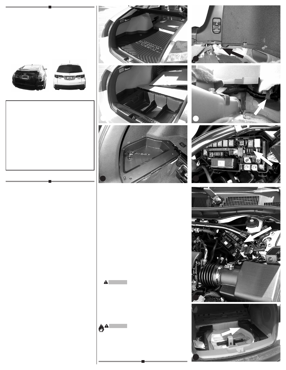
1. CROSSTOUR OnLY
A. Open rear hatch.
Temporarily remove all floor coverings
& center storage bin d-1 d-2.
B. Locate the drivers side cargo tray bolt by
carefully prying open the dust cover. Remove
the bolt and being carefull not to break the clips
that hold the cargo tray pull up and remove
drivers side cargo tray e.
C. locate the blue tow plug at the rear of the
vehicle under the drivers side trim panel f.
It has blue tape holding it to the wire
harness g.
Insert the T-Connector harness into the
vehicle’s Tow-Plug harness and lock into place.
D. Open Hood and locate fuse box on
drivers side h.
Open fuse box and insert 15 amp fuse
provided into empty location shown i.
E. Route the 4-Flat through the driver’s side
trim panel into side storage compartment
and store there when not in use.
F. On driver’s side, locate a flat surface in a out
of the way place and mount the T-Connector’s
black convertor box with the double sided tape.
1. RDX OnLY
A. Open rear hatch.
Temporarily remove all floor coverings,
exposing the spare tire compartment.
Remove spare tire j d-1.
B. Locate blue 6 pin tow plug near foam cargo
tray as shown. It will be taped to the vehicle
electrical harness with blue tape j.
C. Insert the T-Connector harness into the
vehicle’s Tow-Plug harness and lock into place.
D. Locate a flat surface under foam cargo tray
and mount the T-Connector’s black convertor
box with the double sided tape.
Store 4-Flat connector in spare tire
compartment when not in use.
2. BOTH CROSSTOUR & RDX
WARnInG
All connections must be complete for the
T-Connector to function properly. Test and verify
installation with a test light or trailer once installed.
3. Reinstall the plastic trim panels, threshold,
storage covers, floor covering and other items
that may have been removed during installation,
being careful not to pinch or cut the wires
WARnInG
Overloading circuit can cause fires. DO NOT exceed
lower of towing manufacturer rating or:
• Max. stop/turn light: 1 per side (2.1 amps)
• Max. tail lights: (5.6 amps)
Read vehicle’s owners manual & instruction sheet
for additional information.
d
-1
d
-2
g
f
h
j
i