Draw-Tite 118440 T-ONE CONNECTOR User Manual
Draw-Tite For the car
118440-037
Rev. B
08/06/07
ENGLISH
TOOLS NEEDED:
Trim Panel Remover, 10mm Socket &
Ratchet or 10mm Wrench, Wire Crimpers,
Wire Cutters, Test-probe
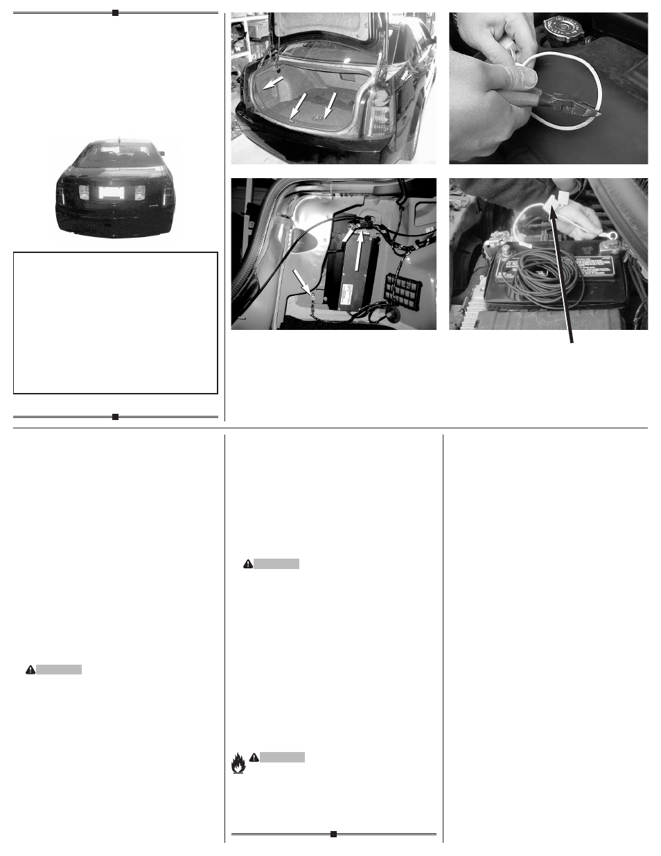
1.
Locate the vehicle wiring inside the vehicle’s
rear cargo area by partially removing the plastic
threshold cover and felt trunk liner
d e
.
2.
The taillight wiring harness will have a
connection point, near each taillight housing,
matching the ends of the T-Connector
e
.
Beginning on the driver’s side, plug the
T-Connector harness containing the yellow wire
in between the vehicle’s mating connectors.
Ensure that the connectors are fully inserted
with locking tabs in place.
3.
On the driver’s side, locate existing ground
stud. Loosen bolt, place screw eyelet on stud
and re-tighten bolt
e
.
WARNING
Make sure all other ground connections are
secure when removing and reattaching the
ground stud.
4.
From inside the trunk, connect the black
12 ga. wire and the red wire from the
T-Connector black box with the supplied
yellow butt connector. Either route the black
wire thru a grommet and along the exterior
frame or follow the existing wiring along the
thresholds into the engine compartment up
to the battery avoiding areas that may pinch
or break the wire.
5.
Disconnect the vehicle’s Negative (-) battery
cable. If not removed, remove the fuse from the
yellow fuse holder (provided). After cutting the
fuse holder wire, attach the ring terminal and
secure to the vehicle’s Positive (+) battery
cable. Connect the other end of the fuse
holder to the black 12 ga. wire, using the
yellow butt connector (provided)
f g
.
6.
Reconnect the vehicle’s Negative (-) battery
cable and install the 10 amp fuse into the
fuse holder from step 6.
WARNING
All connections must be complete for the
T-Connector to function properly. Test and
verify installation with a test light or trailer
once installed.
7.
Secure the remainder of the T-Connector
harness with the cable ties provided, to
prevent damage or rattling and being careful
to avoid any areas that would cut or pinch
the wire. On the driver’s side on the floor of
the rear cargo area, clean a flat area using
a mixture of rubbing alcohol and water. Mount
the T-Connector black box using double-sided
tape provided. Replace the trunk threshold
and felt trunk liner.
NOTE
Store 4-Flat in rear cargo area when not in use.
WARNING
Overloading circuit can cause fires. DO NOT
exceed lower of towing manufacturer rating or:
• Max. stop/turn light: 1 per side (2.1 amps)
• Max. tail lights: (4.2 amps)
Read vehicle’s owners manual & instruction
sheet for additional information.
•
e
•
f
•
g
•
d
Fuse Holder
Porte-Fusible
Portador De Fusibles
Installation Instructions
Directives de Montage
Instrucciones de Instalación
T-Connector
Connecteur en T
Conector en T
READ THIS FIRST:
Read and follow all vehicle warnings and installation
instructions before beginning installation. Wear safety
glasses and use all safety precautions during installation.
LISEZ CECI EN PREMIER:
Lire et observer toutes les consignes de sécurité et les
instructions avant de commencer l’installation. Durant
l’installation, veiller à toujours porter des lunettes de
protection et respecter les mesures de sécurité.
LEA ESTO PRIMERO:
Lea y siga todas las advertencias e instrucciones de
instalación del vehículo antes de empezar la instalación.
Use gafas de seguridad y todas las precauciones de
seguridad durante la instalación.