Draw-Tite 118407 T-ONE CONNECTOR User Manual
Draw-Tite For the car
4. Locate a suitab
le grounding point near the
connector. (Do not drill into vehicle floor or
bed.) Clean dirt and rustproofing from
area. Drill a 3/32" hole and secure
white
wire using e
yelet and screw provided.
CA
UTION
V
erify what is behind any surface prior
to drilling to avoid damage to the vehicle
and/or personal injury. Do not drill into
any exposed surfaces.
W
ARNING
All connections m
ust be complete for the
T-Connector to function properly. Test and
verify installation with a test light or trailer
once installed.
5. Secure the remainder of the
T-Connector
harness with the cable ties provided, to
prevent damage or rattling and being
careful to avoid any areas that would
pinch, cut or melt the wire.
6. Replace both f
oam insulation padding,
wiring access panels, cargo tray, spare
tire hold down nut, & cargo floor panel
removed during installation.
NO
TE
Store 4-Flat connector in rear cargo
area when not in use.
W
ARNING
Ov
erloading circuit can cause fires.
DO NOT exceed lower of vehicle
manufacturer rating or:
• Max. stop/turn light: 7.5 amps per side
• Max. tail lights: 7.5 amps
Read vehicle's owners manual &
instruction sheet for additional information.
ENGLISH
Tools Recommended:
Dr
ill (3/32” Drill Bit), Philips Head
Screwdriver, Trim Panel Remover
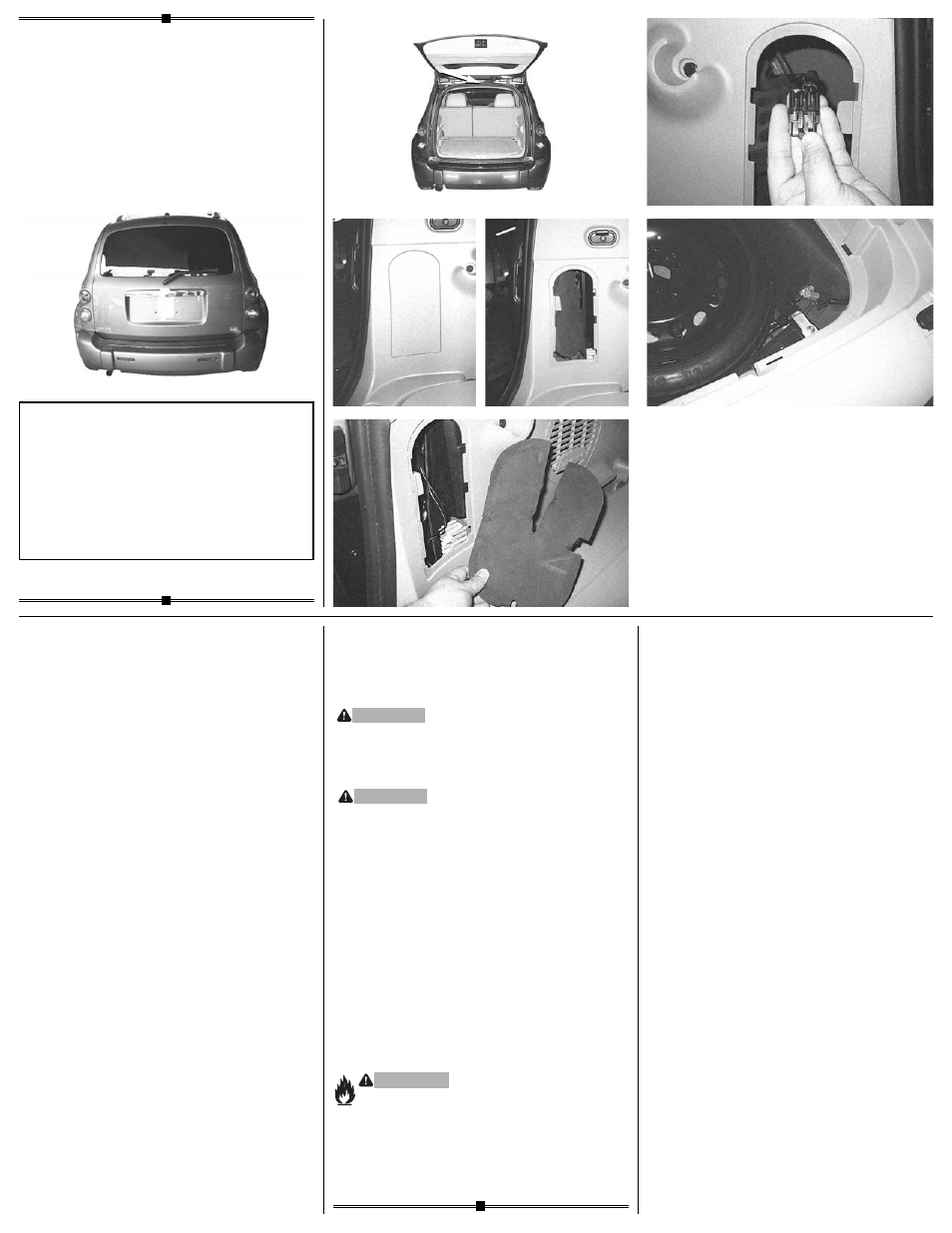
1. Locate the v
ehicle wiring inside the
vehicle's rear cargo area by removing
both of the wiring access side panels
def
.
Carefully remove the foam
insulation padding on each side to access
the taillight connection points
g
.
There will
be connection points matching the ends of
the T-Connector adapter behind each of
the vehicle taillight housings
h
.
NO
TE
There are tw
o sets of taillight connection
points. Use the top set of connection
points for the T-Connector.
2. Beginning on the dr
iver’s side, separate
the vehicle's wiring connectors, being
careful not to break the locking tabs.
All connector surfaces should be clean
and free of dirt. Attach each end of the
T-Connector containing the
y
ellow
wire
.
Ensure that the connectors are fully
inserted with locking tabs in place.
3. Pull up the cargo floor panel, and remo
ve
the cargo tray by unscrewing the spare tire
hold down nut. Pull out cargo tray and set
aside. Route the T-Connector containing
the
green wire behind and under the tr
im
panel, along the vehicle floor near the
spare tire
i
.
Continuing, route wire across
the vehicle and behind the trim panel and
up to the wiring access area. Repeat
step 2 for the passenger’s side using the
T-Connector containing the
green wire
.
18407-037
Rev. A
08/18/05
READ
THIS FIRST:
Read and f
ollow all instructions carefully
before beginning installation.
LISEZ CECI EN PREMIER:
Lire et suivre toutes les instr
uctions
attenrivement avant le montage.
LEA
ESTO PRIMERO:
Lea y siga todas las instr
ucciones
cuidadosamente antes de iniciar la instalación.
•
d
•
f
•
g
•
h
•
i
•
e
Installation Instr
uctions
Directives de Montage
Instrucciones de Instalación
T-Connector
Connecteur en T
Conector en T