Installation instructions, Part numbers – Draw-Tite 4446 GOOSENECK RAIL KIT User Manual
Page 6
Installation Instructions
Part Numbers:
4446
GOOSENECK MOUNTING KIT
Dodge Ram 1500
Short & Long Bed
NOTES:
¾
This rail kit can be used with a 6300, 8339, head only.
¾
Always make sure the ball is fully locked before towing.
¾
Keep the ball and ball pocket well lubricated.
¾
Periodically re-torque all the hitch fasteners.
¾
Check ball, hitch coupler, safety chains and other connections for proper operation every time you tow.
6300/8339 GOOSENECK HITCH INSTALLATION
p
y
p p
p
y
y
Warning:
The tow vehicle manufacturers recommended towing capacities should
UNDER NO CIRCUMSTANCES
be
exceeded.
Check for adequate clearance between the gooseneck trailer and the rear of the cab and the rear of the truck box
before installing hitch.
All trucks have fuel lines, brake lines and electrical wiring located along the vehicle frame where the rail kit
installs. Carefully examine the location of fuel lines, brake lines and electrical wires before installation and be
certain not to damage these when positioning the hitch components. Be careful when drilling holes, cutting
h
t
t l
d ti ht
i
f
t
t
t li it th i t
it
f th
t
sheet metal and tightening fasteners as to not limit the integrity of these systems.
Installation Instructions
1.
Remove plastic inner fender liners on both sides of truck to get access to frame. Liners can either be left off or
modified and reassembled on truck later on. Ask truck owner what they want done.
2.
From underneath the vehicle, remove the clips on the vapor tube and wiring harness, attached to the vehicle rearward
cross member. These will need to be removed to allow the rearward rail to slide into position between the vehicle
bed and frame rails. Also on dual exhaust trucks the hanger mounted to the top of the cross member that interferes
with the rear cross rail will have to be removed Remove bolt and slide hanger out of rubber isolator
with the rear cross rail will have to be removed. Remove bolt and slide hanger out of rubber isolator.
3.
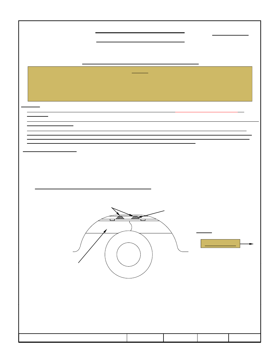
Positioning the cross members by notching the bed seam: Using a saber saw, cut a notch in the bed seam on the
passenger’s side of the vehicle, between the vehicle frame and the bed as shown in Figure 2. Slide the forward cross
member through the notch and above both frame rails. Slide the rearward cross member through the notch cut in the
bed seam and above both frame rails.
Bed Seam
Areas to be notched
Vehicle Forward
Figure 2
Passenger
4.
Position the rearward mounting kit brackets by aligning the slot in the brackets with the threaded studs on the ends
of the rearward rail and the slots on the top and bottom of the vehicle frame rail.
5.
Loosely install the 5/8 hex nut and conical toothed washer attaching the brackets to the rail.
6.
Fish wire the 1/2-13 X 1.75 carriage bolts and 1/4 X 1.00 X 3.00 blocks through the holes in the frame, and through
th h l i th b
k t
L
l i t ll th 1/2 h
t
d l k
h
g
Side Frame
Rail
z
2008, 2009, 2010, 2011 Cequent Performance Products
Sheet 6 of 8
4446N
6-9-11
Rev. E
the holes in the brackets. Loosely install the 1/2 hex nuts and lock washers.
7.
Install the forward mounting kit brackets by aligning the hole in the brackets with the threaded studs on the ends of
the rail. Loosely install the 5/8 hex nut and conical toothed washer attaching the brackets to the rail.
8.
Loosely install the clamp brackets using the 1/2-13 X 5.50 carriage bolts, conical toothed washers and hex nuts.