Draw-Tite 4438 GOOSENECK RAIL KIT User Manual
Page 8
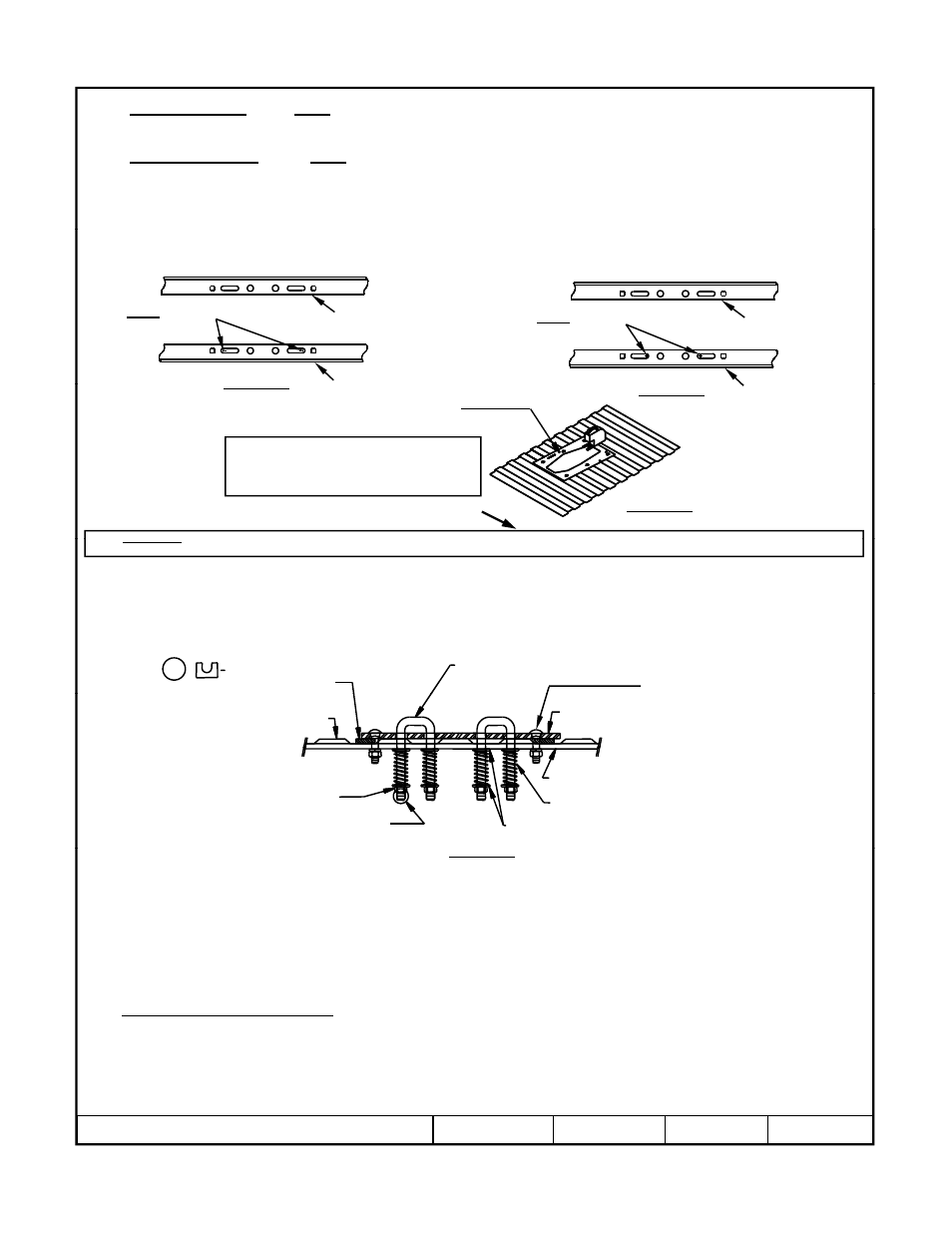
9a.
For 6300 & 8339 use the outer edges of the long slots in the rearward cross member as a template to drill 5/8”
diameter holes through the truck bed as shown in Figure 9a. Not all holes can be drilled from under the vehicle, but
should be done later from inside the bed.
9b.
For 83391 & 83399 use the inner edges of the long slots in the rearward cross member as a template to drill 5/8”
diameter holes through the truck bed as shown in Figure 9b. Not all holes can be drilled from under the vehicle, but
should be done later from inside the bed.
10.
Align the holes on the template (provided with the gooseneck hitch) with the holes previously drilled through the
bed (see Figure 10). Be sure that the template is properly oriented toward the front of the vehicle. Center punch the
h l th t ill b
d t
t th
i
i th b d If th
hi l i
i
d ith b d li
ti
f th b d
Figure 9a
Forward cross
member
Rearward cross member
Use outer edges to
drill 5/8” holes
holes that will be used to cut the opening in the bed. If the vehicle is equipped with a bed liner, a section of the bed
liner must be cut away so that the gooseneck hitch can contact the bed corrugations.
6300/8339 Hole Locations
Fi
9b
Forward cross
member
Rearward
Use inner edges to
drill 5/8” holes
83391/83399 Hole Locations
Figure 9a
WARNING: The fuel tank and/or other vehicle components are located below some of the holes A wood or metal shield must
Figure 10
Template p/n 5978 for use with 6300 head
Template p/n 114234 for use with 8339 head
Template p/n 114523 for use with 83391/83399 heads
Durable and reusable stainless steel templates are also
available. A time saver for cutting bed liner and bed.
Template p/n 6467 for use with 6300 head
Template p/n 6425 for use with 8339 head
Template p/n 58384 for use with 83391/83399 heads
Vehicle forward
Figure 9b
Rearward
cross member
11.
Drill 1/4” pilot holes (size will depend on width of blade in saber saw).
12.
Cut out the truck bed and file edges as needed.
13.
Install the hitch into the opening.
14.
Use hitch as a guide to drill the 5/8” diameter holes for the forward cross member. Also, drill 5/8” diameter U-Bolt
holes if installing a 6300 or 8339 gooseneck hitch.
WARNING: The fuel tank and/or other vehicle components are located below some of the holes. A wood or metal shield must
be placed between the frame and the fuel tank to prevent puncturing the fuel tank when the drill breaks through the bed.
5/8” X 2.50” Carriage Bolt
L k
h
5
5/8” u-bolt 5-1/2” length – 2 places
Safety chain attachment
5/16” x 2” x 1” shims
4 places p/n 5979
Lock washer
Hex Nut
4 Places
Figure 11
Large flat washer – 8 places
Spring – 4 places
Forward cross member
Gooseneck
platform
3 visible full bolt
threads required
5/8” – 18 locking jam nut
4 places
Truck bed corrugation
15.
Before installing the 5/8” carriage bolts through the hitch, the U-Block shims (Part Number 5979) must be placed
between the hitch and the bed and between the cross members and the bottom of the bed. These shims are necessary
to prevent the bed corrugations from collapsing when the bolts are tightened (see Figure 11).
16.
Align the forward cross member with the 5/8” diameter drilled holes.
17.
Install the 5/8” X 2.50” carriage bolts through the hitch, shims and cross members. Secure with lock washers and
nuts. Torque nuts to 150 ft.-lb. (203 N-m).
18.
Tighten the 5/8” hex nuts that attach the forward cross member to the frame brackets. Torque nuts to 150 ft.-lb. (203
N-m).
19
6300
8339
i
ll h (2)
l
h
h h hi h
d f
d
h
hi l i
ll h
Figure 11
19.
For 6300 and 8339 Installations: Install the (2) U-Bolts through the hitch and from under the vehicle install the
large flat washer over the U-Bolt followed by a spring, another large flat washer and secure with a thin 5/8” jam nut.
Repeat for the other legs of the U-Bolts. The 5/8” jam nuts are tightened until (3) threads are visible past the bottom
of the jam nut.
20.
Reattach the brake line to the inside of the vehicle driver’s side frame. If the brake line cannot be reattached using
the existing hardware, use the cable tie to attach the line to the forward hitch cross member.
21.
Reinstall the exhaust, if necessary. Raise the spare tire to its stored position.
z
2008, 2009 Cequent Performance Products
Sheet 8 of 8
4438N
4-3-09
Rev. E