Installation instructions, Part numbers – Draw-Tite 4437 GOOSENECK RAIL KIT User Manual
Page 4
Installation Instructions
Part Numbers:
4437
HIDE-A-GOOSE
Ford F-150
NOTES:
This section of instructions refers to installing the 6300, 630044 or 8339 head only.
Always make sure the ball is fully locked before towing.
Keep the ball and ball pocket well lubricated.
Periodically re-torque all the hitch fasteners.
Check ball, hitch coupler, safety chains and other connections for proper operation every time you tow.
Warning:
The tow vehicle manufacturers recommended towing capacities should
UNDER NO CIRCUMSTANCES
be exceeded.
Check for adequate clearance between the gooseneck trailer and the rear of the cab and the rear of the truck box before installing hitch.
All trucks have fuel lines, brake lines and electrical wiring located along the vehicle frame where the rail kit installs. Carefully examine the
location of fuel lines, brake lines and electrical wires before installation and be certain not to damage these when positioning the hitch
components. Be careful when drilling holes, cutting sheet metal and tightening fasteners as to not limit the integrity of these systems.
6300/630044 Remove-A-Ball and 8339 Fold Down Gooseneck Installation
1.
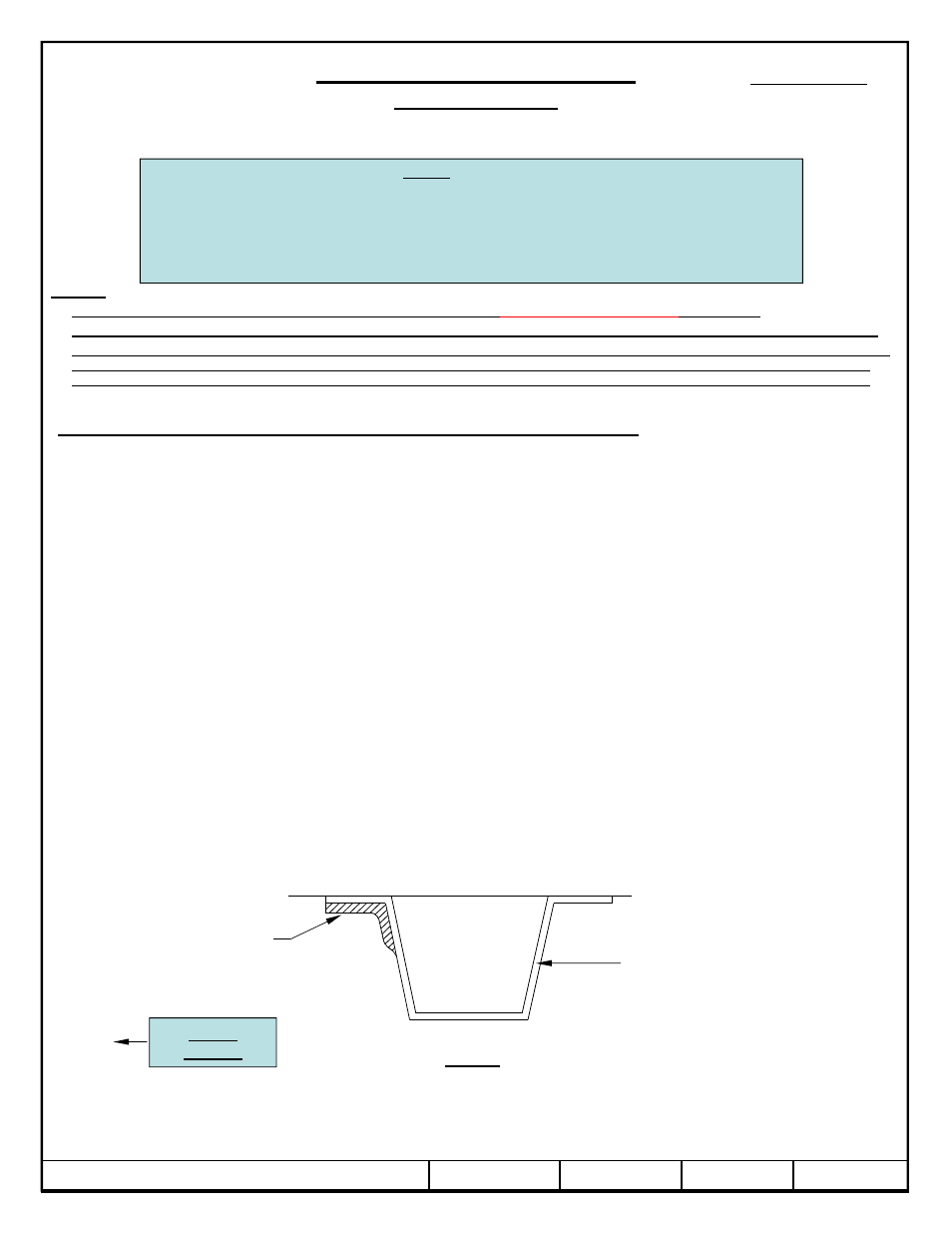
On some model years, the rearward hat section of the vehicle bed will have two sheet metal
reinforcements that will need to be flattened or removed from each side of the vehicle, see Figure 2 for
locations.
2.
Slide the forward and rearward cross members between the frame rail and the bed of the vehicle as shown
in Figure 3. The forward cross member has (2) additional holes centered between the long slots.
3.
On older model trucks remove the jounce block from the underside the frame rails and use the pull wire to
insert the carriage bolts and blocks into the bracket mounting locations. On newer model trucks you can
pull fasteners through slot on inside of truck frame rail.
© 2007, 2008, 2009, 2011 Cequent Performance Products
Sheet 4 of 6
4437N
8-10-11
Rev. H
pull fasteners through slot on inside of truck frame rail.
4.
Install the hitch frame brackets by aligning the threaded studs on the ends of cross members to the outer
set of slots of the brackets, then aligning the mounting slots to the carriage bolts inserted in installation
step 3.
5.
Loosely install the flat washers, lock washers, and hex nuts to the frame bracket.
6.
With the rearward cross member positioned against the rearward hat section of the bed, torque the 5/8-11
GR5 fasteners that attach the rearward cross member to the brackets to150 ft.-lb. (203 N-m). Torque the
1/2-13 GR5 fasteners that attach the brackets to the vehicle frame rails to 75 ft.-lb. (102 N-m).
7.
If removed re-install jounce blocks to the underside of the frame rails.
Figure 2
Rearward hat
section between
truck bed and frame
rails
Vehicle
Forward
Area to be
flattened or
removed