Installation instructions – Draw-Tite 4435 GOOSENECK RAIL KIT User Manual
Page 6
Installation Instructions
GOOSENECK MOUNTING KIT
Dodge Ram 2500/3500 Heavy Duty
Short & Long Bed, & All Megacabs
6300/8339/83391/83399 GOOSENECK HITCH INSTALLATION
Part Numbers:
4435
NOTES:
¾
This rail kit can be used with a 6300, 8339, 83391 or 83399 head only.
¾
Always make sure the ball is fully locked before towing.
¾
Keep the ball and ball pocket well lubricated.
¾
Periodically re-torque all the hitch fasteners.
¾
Check ball, hitch coupler, safety chains and other connections for proper operation every time you tow.
Warning:
The tow vehicle manufacturers recommended towing capacities should UNDER NO CIRCUMSTANCES be
The tow vehicle manufacturers recommended towing capacities should UNDER NO CIRCUMSTANCES be
exceeded.
Check for adequate clearance between the gooseneck trailer and the rear of the cab and the rear of the truck box
before installing hitch.
All trucks have fuel lines, brake lines and electrical wiring located along the vehicle frame where the rail kit
installs. Carefully examine the location of fuel lines, brake lines and electrical wires before installation and be
certain not to damage these when positioning the hitch components. Be careful when drilling holes, cutting
sheet metal and tightening fasteners as to not limit the integrity of these systems.
Installation Instructions
Installation Instructions
1.
Lower the vehicle exhaust by removing the retaining clips from the rubber exhaust hanger and then sliding the
rubber exhaust hanger from the exhaust hanger hooks. Lower the spare tire to provide clearance for the cross
member installation. On 2010 and later model year vehicles, temporarily remove the ground wire located on the
outside of the Driver’s side frame rail.
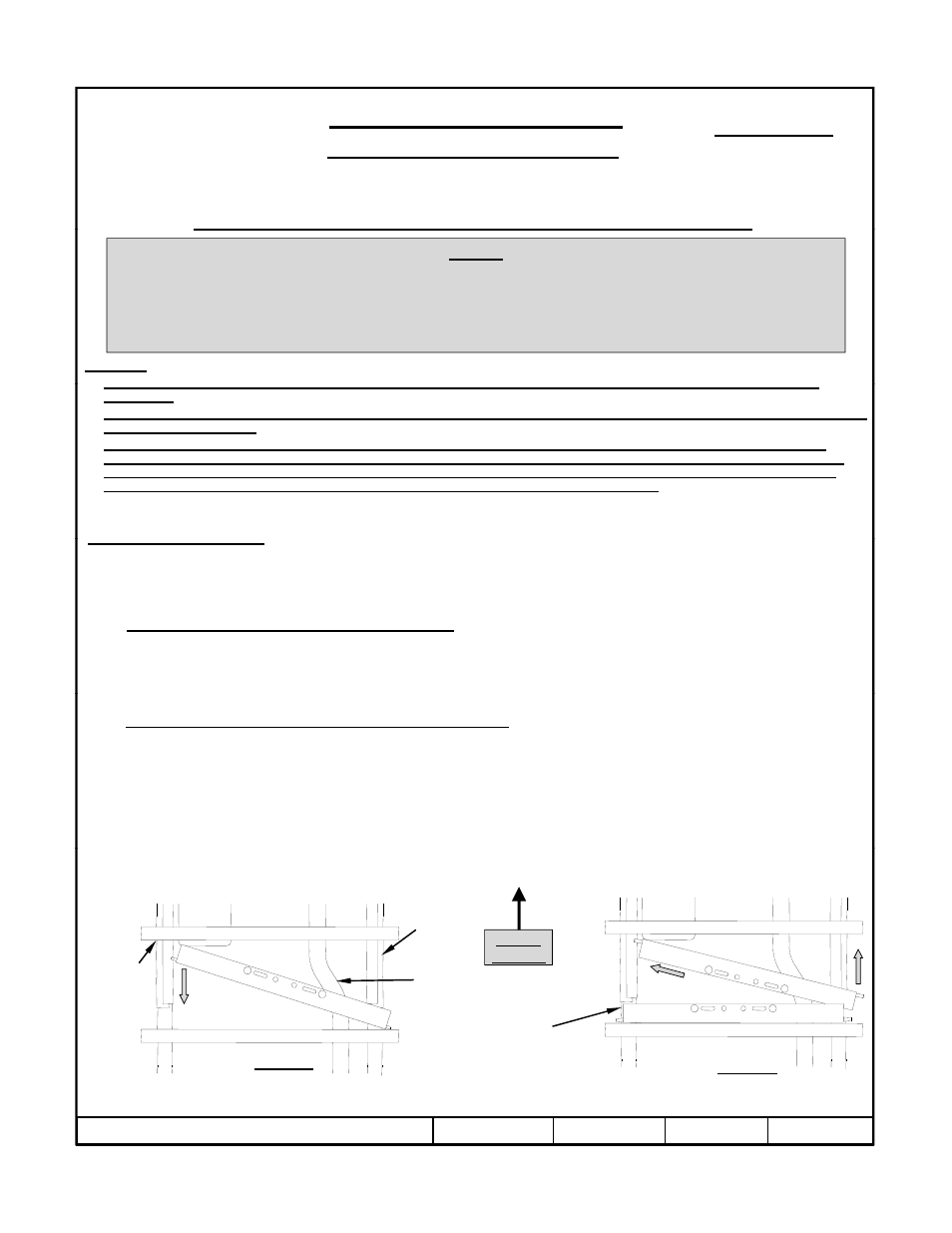
2a. Positioning the cross members from underneath: Place the cross members into position between the top of the
frame and under the bed as shown in Figure 2, starting with the rear cross member. Note: the cross members in this
kit are the same, but they face different directions as shown in Figure 1. Slide the rear cross member between the
driver’s side frame and the vehicle bed, then over the exhaust (Figure 2a). Slide the right end of the cross member
over the passenger’s side frame and back against the rear bed support. Install the forward cross member as shown in
i
2b
Figure 2b.
2b.
Positioning the cross members by notching the bed seam: Using a saber saw, cut a notch in the bed seam on the
passenger’s side of the vehicle, between the vehicle frame and the bed as shown in Figure 3. Slide the forward cross
member through the notch cut in the bed seam and above both frame rails. Then slide the rearward cross member
through the notch cut in the bed seam and above both frame rails.
Vehicle
Forward
Front bed
support
Exhaust
Passenger’s side
frame
z
2007, 2008, 2009, 2010 Cequent Performance Products
Sheet 6 of 8
4435N
1-12-10
Rev. J
Figure 2a
Figure 2b
Rear
cross member
in position