Draw-Tite 3203 ROUND BAR WT. DIST. User Manual
Installation instructions
112901-02/27/12 REV.B
©2012 CEQUENT PERFORMANCE PRODUCTS, INC.
Litho in USA
SMALL PARTS
PACKAGES 66014K AND 61224
For Installation Assistance or Technical Help, Call 1-800-758-0869
INSTALLATION INSTRUCTIONS
Heavy Duty Round Bar Adjustable
Weight Distributing Hitches
PLYMOUTH, MI.
DEALERS: Give these instructions to your customers.
INITIAL SET-UP
1. Line up
tow vehicle and trailer on level pavement,
in straight-ahead position, uncoupled.
2. Level the trailer and measure and record the
distance from the ground to the top of the ball
socket (dimension Fig. 1).
3. Select a hitch ball with a diameter that matches
the trailer coupler size. The three most common
sizes are 1-7/8", 2", and 2-5/16". Select ball with
1-1/4" or 1" threaded shank that is V-5 rated equal
to or greater than trailer gross vehicle weight
rating (GVWR).
WARNING: Raised balls usually have reduced load
ratings. Ball rating MUST equal or exceed trailer GVWR.
4. Attach hitch ball to the ballmount (G). A standard height hitch balls
with 1-1/4" shanks are supplied with lock washers and nuts (If you must use
a 1” shank ball, use
reducer
bushing (B) to reduce hole size in ballmount (G)
to 1”). Always use a lock washer and place washer next to nut. Unless other-
wise specified by ball manufacturer torque ball nut to 450 ft/lbs for 1-1/4" nut,
250 ft/lbs for 1" nut.
5. Some installations may require a longer hitch bar (D). Extended bumper guards, pickup truck "caps", or rear mounted spare tires
can limit turn angles unless a longer bar is used. Individual hitch bars (D) are available in various sizes.
6. Insert the hitch bar (D) into the hitch box and install a pull pin. Place ballmount (G) onto hitch bar and move up or down for proper
height. Hitch bar may be used in either the up or down position (see Fig. 2).
NOTE: Ball height should be greater
than coupler height (measured in step 1) to compensate for vehicle "squat”
(approximately 3/4” to 1”).
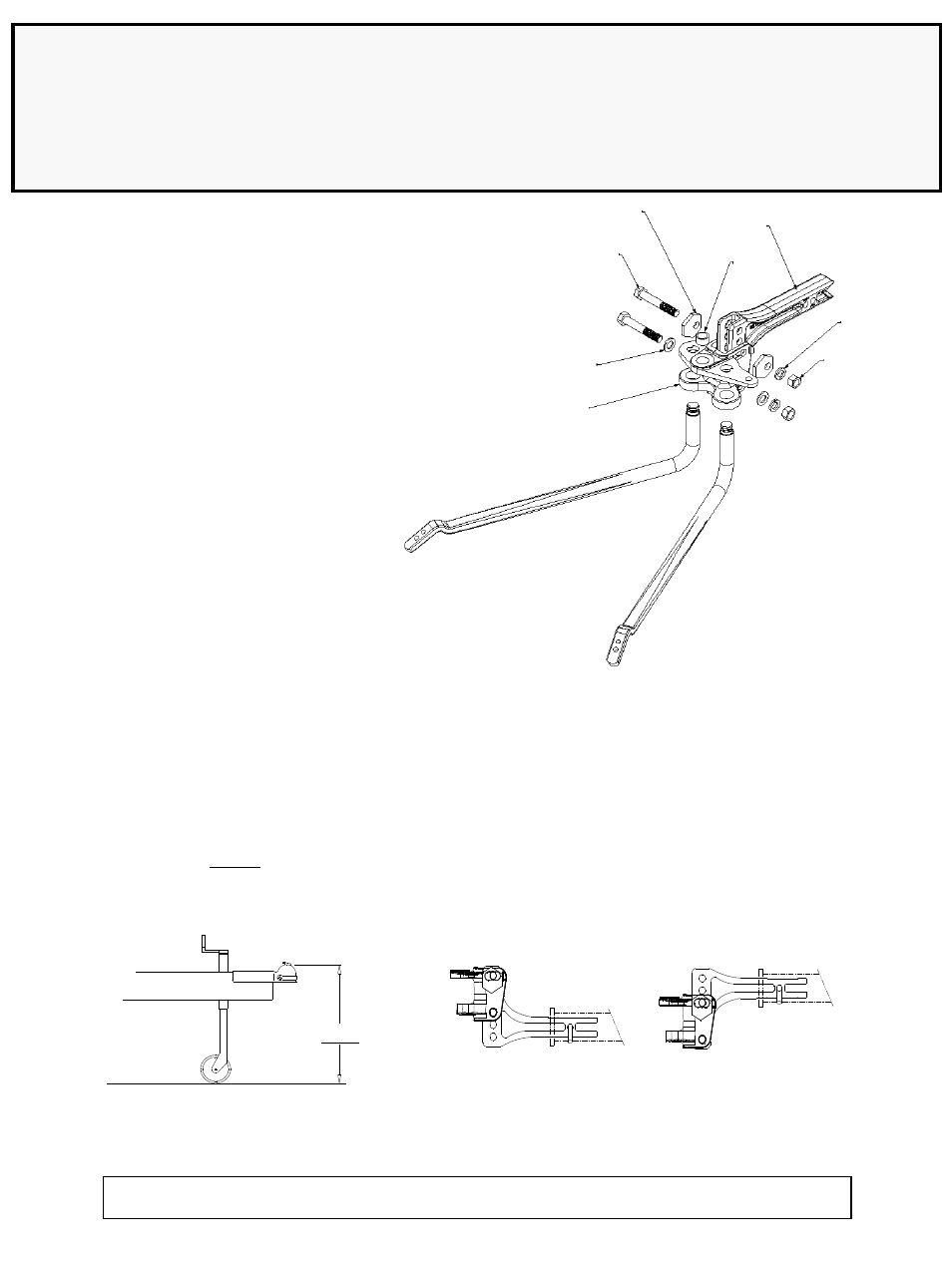
Fig. 1
Fig. 2
D
L
K
G
F
J
E
B
* SHOWN WITH NEW INTEGRATED
CAM SPRING BARS