Draw-Tite 118253 OEM WIRING HARNESS User Manual
Dg h, English
READ THIS FIRST:
Read and follow all vehicle warnings and
installation instructions before beginning installation.
Wear safety glasses and use all safety precautions
during installation.
LISEz CECI En PREmIER:
Lire et observer toutes les consignes de sécurité et les
instructions avant de commencer l’installation. Durant
l’installation, veiller à toujours porter des lunettes
de protection et respecter les mesures de sécurité.
LEA ESTO PRImERO:
Lea y siga todas las advertencias e instrucciones
de instalación del vehículo antes de empezar la
instalación. Use gafas de seguridad y todas las
precauciones de seguridad durante la instalación.
118491-037
Rev. B
03/08/2010
Installation Instructions
Directives de montage
Instrucciones de Instalación
T-Connector
Connecteur en T
Conector en T
Honda Pilot
ENGLISH
TOOLS REQUIRED:
Trim Panel Remover, Test-probe
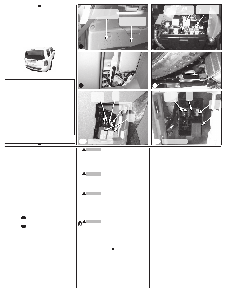
1. Open rear door and fold rear seat forward.
Locate and open the storage compartment
on the driver’s side of the cargo area
d
.
2. Locate the grey tow plug by opening the
access panel inside of the storage compartment
e
. Insert the convertor box into the vehicle’s
grey tow plug.
3. Locate the fuse panel in the rear cargo area on
the driver’s side next to the rear seats that are in
the folded position
d
. Open fuse compartment
using trim panel remover. Insert relays and fuses
as described below.
– Kit #118253 - 2 relays and fuses as shown in
Photo .
– Kit #118491 - 1 relay and fuses as shown in
Photo .
4. Locate vehicle fuse box in engine compartment
on driver’s side. Insert fuses into positions
as shown
g
.
5. Locate the large grey housing under the vehicle
bumper on the driver’ side
h
. Remove protective
cap, being careful not to break the locking tabs.
Ensure that the mating surfaces are free of dirt.
Plug towing harness into grey tow plug.
Be careful not to damage the locking tabs and
be sure that connectors are fully inserted with
locking tabs in place. Route the T-Connector
harness rearward to the back of the fascia of
the bumper.
e
WARnInG
Route the wire being careful to avoid any hot
pipes, heat shields, the fuel tank or any other
points that may pinch or break the wire.
7. Secure 4-Flat/ 7-Way tow harness to hitch.
Bracket not included.
WARnInG
Secure the remainder of the T-Connector harness
under the bumper with cable ties provided, being
careful to avoid any areas that would cut or pinch
the wire.
WARnInG
All connections must be complete to function
properly. Test and verify installation once
installed.
For initial test, reset vehicle electrical system by
temporarily removing the key from the ignition.
Test the installation with a test light or trailer.
WARnInG
Overloading circuit can cause fires. DO NOT
exceed lower of vehicle manufacturer rating or:
• Max. stop/turn light: 2 per side (4.2 amps)
• Max. tail lights: (7.5 amps)
Read vehicle’s owners manual &
instruction sheet for additional information.
d
g
h
Storage Compartment
Compartiment de rangement
Compartimiento de almacenamiento
Fuse Compartment
Compartiment à fusibles
Compartimiento de fusibles
30 amp box fuse
Boîtier à fusibles 30 ampères
Caja de fusibles 30 amperios
20 amp fuse
Fusible 20 ampères
Fusible de 20 amperios
20 amp
20 ampères
20 amperios
Empty
Vide
Vacío
7.5 amp
7,5 ampères
7.5 amperios
Empty
Vide
Vacío
7.5 amp
7,5 ampères
7.5 amperios
Relay
Relais
Relé
20 amp
20 ampères
20 amperios
118253 Harness
C-1
C-1
C-2
C-2
118491 Harness
Relay
Relais
Relé