Mounting, Bench test instructions, Wiring – Draw-Tite 5500 ACTIVATOR II BRAKE CONTROL User Manual
Page 2
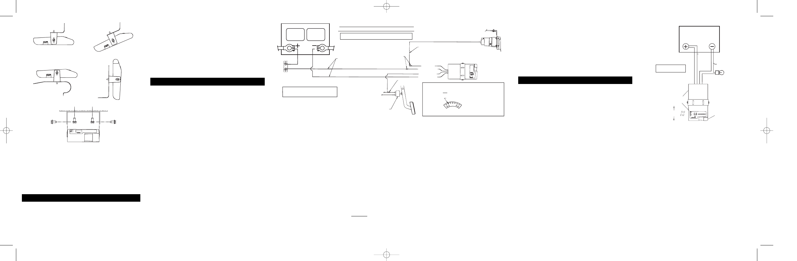
UNDER DASH
TOP OF DASH
VERTICAL
ANY ANGLE
IMPORTANT: MAKE SURE AREA BEHIND PANEL IS CLEAR
BEFORE DRILLING.
USE BRACKET AS TEMPLATE TO MARK HOLE LOCATIONS.
DRILL (2) 1/8" DIA. HOLES AND MOUNT BRACKET WITH
SCREWS PROVIDED.
MOUNT BRAKE CONTROL TO BRACKET USING THE
REMAINING (2) SCREWS.
MOUNTING
2. Hold the mounting bracket in the position selected and
mark hole locations through the slots in the bracket
3. Using a 1/8" dia. bit, drill holes in the marked locations.
4. With a screwdriver or a 1/4" nut driver, secure the
bracket in place using (2) self tapping screws (provided).
Be careful not to strip the holes by over-tightening.
5. Mount the brake control unit in the bracket using the
other (2) self tapping screws as shown in the illustration.
WARNING: Do not connect the black “BATTERY” wire to
the fuse panel or tie into accessory wiring. Connecting
to existing wiring may damage vehicle wiring and cause
trailer brake failure.
FOR TOW VEHICLES EQUIPPED WITH FACTORY TRAILER
TOWING PACKAGES:
Wire per tow vehicle manufacturer's instructions.
NOTE: Make sure that the tow vehicle's Brake Control
Battery Feed circuit is capable of carrying enough current to
supply trailer brake requirements (check tow vehicle manu-
facturer's instructions and trailer brake manufacturer's
information). If the circuit does not meet the trailer's
requirements, wire directly to the battery per steps 1
through 7.
FOR TOW VEHICLES WITHOUT FACTORY TRAILER
TOWING PACKAGES:
1. Disconnect the tow vehicle's negative (-) battery cable.
2. Mount a 30 Amp auto-reset circuit breaker as close to
the positive (+) battery terminal as possible. Using 10 Ga.
stranded wire and crimp type ring terminals connect the
"BATT" side of the circuit breaker to the positive battery ter-
minal.
NOTE: When passing wire through sheet metal always go
through an existing grommet, add a grommet or use
silicone rubber to insulate the wire from the hole.
3. Feed one black and one white, 10 Ga. stranded wire from
the Brake Control location to the tow vehicle's battery area.
4. Connect the black wire to the "AUX" side of the circuit
breaker with a ring terminal.
5. Connect the white wire to the negative battery post with
a ring terminal.
6 Attach the Control's black "BATTERY +" wire to the wire
(black) connected to the "AUX" side of the circuit breaker
using a butt connector.
7. Connect the control's white "GROUND" wire to the wire
(white) leading from the negative battery terminal with
another butt connector.
IMPORTANT: A brake control that is not properly grounded
may operate intermittently or not at all. Recheck to make
sure that the white "GROUND -" wire is connected to the (-)
negative battery terminal and that the black "BATTERY +"
wire is attached to the (+) positive battery terminal.
8. For tow vehicles other than 1989-91 Ford E and F
series trucks and vans:
Determine which side of the stoplight switch is the cold
side. To determine the cold side probe the terminals of the
switch with a test light until one is found that is only on
when the brake pedal is depressed.
Using the wire tap provided, splice the brake control's red
"STOPLIGHT" wire to the attached to the cold side of the
stoplight switch as determined above.
For 1989-91 Ford E and F series trucks and vans with
anti-lock brakes:
Find the crescent shaped connector located on the steering
column (turn signal harness). The connector has two rows
of wires, one row has four wires (inside row) the other has
seven.
The wire needed is the light green wire, second in from the
row of seven (see wiring diagram above).
Using the wire tap provided, splice the brake control's red
"STOPLIGHT" wire to the light green wire.
9. Secure all loose wires with cable ties so that they will
not be damaged and reconnect battery. See vehicle's
owners manual for special re-connection instructions.
10.Test installation:
Without a trailer connected, push the brake pedal.
A single . (decimal point) should light up on the Display.
If the decimal point does not light or if OL or Er is shown
go to the Trouble Shooting section.
12 VOLT BATTERY OF TOW VEHICLE
THIS ELECTRONIC BRAKE CONTROL IS FOR USE
ON 12 VOLT NEGATIVE GROUND SYSTEMS ONLY
IMPORTANT: READ AND FOLLOW ALL WARNINGS AND
CAUTIONS ON TOW VEHICLE BATTERY
IMPORTANT: DO NOT REVERSE BLACK AND
WHITE WIRE CONNECTIONS. DAMAGE TO
THE BRAKE CONTROL UNIT MAY OCCUR.
STOPLIGHT SWITCH
CONNECT TO COLD SIDE
(ON ONLY WHEN PEDAL IS PUSHED)
WIRE TAP
(SUPPLIED)
BUTT CONNECTORS
(NOT SUPPLIED)
USE 10 GA. WIRE
USE 10 GA. WIRE
DISCONNECT NEGATIVE (-)
CABLE BEFORE WIRING
BRAKE CONTROL UNIT
30A AUTO-RESET
CIRCUIT BREAKER
(NOT SUPPLIED)
TRAILER
CONNECTOR
BRAKE CONTROL
SPECIAL INSTRUCTIONS FOR FORD E AND F SERIES TRUCKS
AND VANS, 1989 - 91, WITH ANTI-LOCK BRAKES
DO NOT CONNECT TO STOPLIGHT SWITCH
ON THESE VEHICLES
LIGHT GREEN WIRE
TURN SIGNAL HARNESS
CONNECTOR UNDER DASH
NEAR STEERING COLUMN
SPLICE RED STOPLIGHT WIRE TO LIGHT GREEN
WIRE USING THE WIRE TAP CONNECTOR SUPPLIED
BRAKE BLUE
BATTERY + BLACK
STOPLIGHT RED
GROUND - WHITE
BATT
AUX
IMPORTANT: READ AND FOLLOW
ALL WARNINGS AND CAUTIONS
SHOWN ON BATTERY
MANUAL CONTROL
SYNC CONTROL
WHITE WIRE IS
CONNECTED TO
NEGATIVE -
BLACK WIRE IS
CONNECTED TO
POSITIVE +
ONLY CONNECT BULB
TO NEGATIVE TERMINAL
WHEN NEEDED
ONLY CONNECT
RED WIRE
WHEN NEEDED
USE A SOCKET OR SOLDER
WIRES TO BULB
STANDARD 1156
AUTOMOTIVE BULB
RED WIRE
WHITE WIRE
BLACK WIRE
BLUE WIRE
OUTPUT CONTROL
MORE OUTPUT
LESS OUTPUT
12 VOLT BATTERY OF TOW VEHICLE
BENCH TEST INSTRUCTIONS
1. Wire as shown at right. Set the Output control to
maximum (+) and set the Sync control to minimum (-).
NOTE: If at any time during the bench test, the display shows
OL make sure that the blue "BRAKE" wire is not shorted to the
"-" battery terminal or the white "BATTERY -" wire.
If at any time, the display shows Er return the unit to your
Draw-Tite dealer for further evaluation.
2. Test "Standby Condition"
Hold the red "STOPLIGHT" wire on the "+" battery terminal. The
display should show a single . (decimal point). This indicates
correct wiring and that the control is ready.
Disconnect the red "STOPLIGHT" wire from the battery.
3. Test Brake Pedal Activation
Firmly ground the light bulb to the "-" terminal of the battery.
Re-attach the red "STOPLIGHT" wire to the "+" battery terminal.
The display should step up to 10 and the bulb should start
out dim and slowly get brighter (unhook and re-attach the
red wire as many times as necessary to confirm this)
With the red wire still hooked up, slowly move the Output
Control down to (-). The display should count down to 0
and the bulb should dim and go off.
Slowly move the Output Control back up to (+), the Display
should go back to 10 and the bulb should return to full brightness.
Slowly move the Sync Control to maximum (+). The
display should change to Sync mode and count up to 9
0
.
Disconnect and reconnect the red wire. The bulb should
light brightly with no delay and the Display should read 10.
Disconnect the red wire.
4. Test Manual Activation
With the Output Control still set at maximum, slowly
activate the Manual Control button.
The bulb should start to dim and get brighter and the dis-
play should count up to 10 as the Manual Control is pushed.
While holding the Manual Control all the way in, rotate the
Output Control up and down. As the output changes the
bulb should go bright and dim and the display should
read 0 to 10.
5. Defective Unit
If the Brake Control unit does not function as described,
return it for service or replacement.
1. Determine a suitable mounting location.
A) The unit must be mounted securely to a solid surface.
B) The unit must be easily reached by the driver.
C) The area behind the mounting location must be clear
so nothing will be damaged when drilling.
WIRING
05500-037 2/6/03 English 3/6/03 2:05 PM Page 2