Draw-Tite 24811 SPORTFRAME HITCH User Manual
Fasteners typical both sides of vehicle, Installation instructions, Volvo c30
Installation Instructions
Volvo C30
Part Numbers:
77182
24811
60897
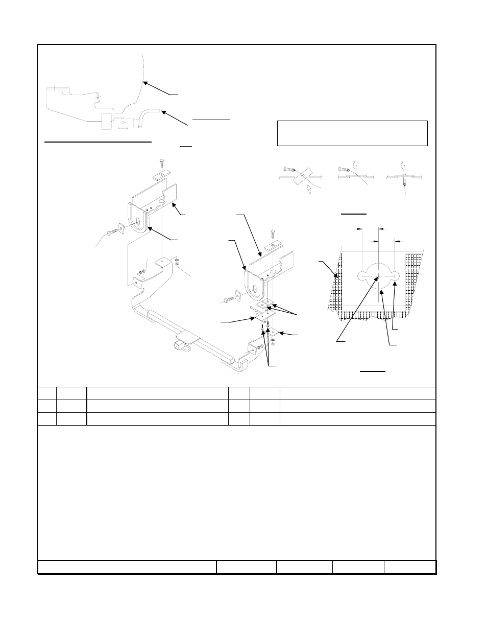
Hitch Shown In Proper Position
Wiring Access Location: PC3, PC4
Equipment Required: Tin Snips
Wrenches: ¾”
Drill Bits: 3/8”, 1” Hole Saw
1.
Remove passenger’s side exhaust hanger by removing (2) bolts which attach exhaust hanger bracket to frame. Retain bolts for reinstallation.
2.
Raise hitch into position and temporarily attach using only tow hook mounting fasteners.
3.
Mark exhaust heat shield at each frame bracket flange for trimming to allow flange to sit flat against vehicle frame.
4.
Using holes in frame bracket flanges, mark hole locations on frame rails.
5.
Take down hitch. Drill access holes in frame rails in areas marked in step 4 (See figure 2)
6.
Reverse fishwire ½” carriage bolts and blocks thru access holes as shown in figure 3.
7.
Raise hitch back into position, being careful not to push carriage bolts back into frame. Secure with fasteners as shown in Figure 1. Tighten all
½-13 GR5 fasteners with torque wrench to 75 Lb.-Ft. (102 N*M)
8.
Reattach passenger’s side exhaust hanger bracket with existing fasteners. Because hanger bracket will overlap hitch frame bracket, it will be
necessary to space down exhaust hanger using ¼ x 1 x 2 blocks as shown above.
Tighten all ½-13 GR5 fasteners with torque wrench to 75 Ft.-Lb. (102 N*M)
Tighten all M6 fasteners with torque wrench to 62 In.-Lb. (7 N*M)
Rev. A
3-6-08
24811N
Sheet 1 of 3
z
2008 Cequent Towing Products
Hex Nut – ½-13
Qty. (4)
6
Carriage Bolt – ½-13 x 1.75 GR5
Qty. (2)
3
Lock Washer – ½”
Qty. (4)
5
Block – ¼ x 1 x 2
Qty. (4)
2
Block - ¼ x 1 x 3 (Square Hole)
Qty. (2)
4
Hex Bolt – ½-13 x 1.50 GR5
Qty. (2)
1
Note: check hitch frequently, making sure all fasteners and ball are properly tightened. If hitch is removed, plug all holes in trunk pan or other body panels to
prevent entry of water and exhaust fumes. A hitch or ball which has been damaged should be removed and replaced. Observe safety precautions when working
beneath a vehicle and wear eye protection. Do not cut access or attachment holes with a torch.
This product complies with safety specifications and requirements for connecting devices and towing systems of the state of New York, V.E.S.C. Regulation V-5
and SAE J684.
2000 LB (908 Kg) Max Gross Trailer Weight
200 LB (90.8) Max Tongue Weight
Do Not Exceed Lower of Towing Vehicle
Manufacturer’s Rating or
Drawbar must be used in the
Rise position only.
Drawbar Kit:
3593
Fastener Kit: 24811F
Form F206 Rev A 5605
A. Insert bolt and
Block into frame
B. Align block on
Access hole
C. Pull bolt thru
block
Figure 3
Reverse fishwiring procedure
5/8” (16mm)
5/8” (16mm)
3/8” hole (2)
Drill first
Hole location
Marked in
step 4
1” dia. – drill
After 3/8” holes
Are drilled.
Figure 2
Drilling of Access Holes
5
6
5
6
1
2
3
4
Fasteners typical both
Sides of vehicle
Exhaust hanger
bracket
Existing exhaust
Hanger bolts
2
Vehicle Frame Rail
Vehicle Tow Hook
Fascia
Frame
Bracket
Flange
Heat shield
Trimmed for
frame bracket
flange