Draw-Tite 24821 SPORTFRAME HITCH User Manual
Installation instructions, Pontiac g8, Figure 2
Installation Instructions
Pontiac G8
Part Numbers:
77193
24821
60208
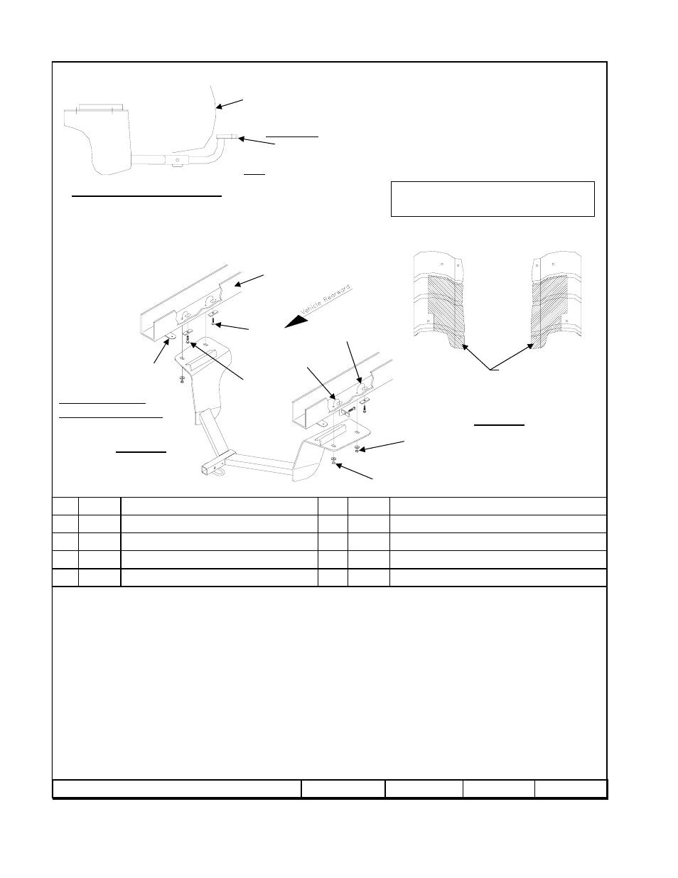
Hitch Shown In Proper Position
Wiring Access Location: PC3, PC4
Equipment Required: Pull wire (provided)
Wrenches: 10mm, 13mm, 15mm, 11/16”, ¾”
Drill Bits: None
1.
Remove each muffler as follows:
a) Remove (2) bolts which attach exhaust hanger bracket to rear of frame rail
b) Remove (2) bolts forward of muffler at flange
2.
Remove heat shield from each side by removing (4) bolts from each shield. Cut each heat shield as shown in Figure 2 to allow frame access
with hitch side brackets. Reinstall heat shields using (3) of the (4) bolts removed (4
th
bolt will not be used and may be discarded).
3.
Using pull wires provided, install carriage bolts and spaces into frame rail through access slots as shown: 7/16” carriage bolt and spacer with
smaller hole into forward hole; ½” carriage bolt and spacer with larger hole into rearward hole.
4.
Raise hitch into position, being careful not to push bolts and spacers back into frame. Secure with conical toothed washers and nuts.
5.
Reinstall mufflers.
Tighten all ½-13 GR5 fasteners with torque wrench to 75 Lb.-Ft. (102 N*M)
Rev. A
8-12-08
24821N
Sheet 1 of 3
z
2008 Cequent Towing Products
Pull Wire 7/16”
Qty. (2)
Carriage Bolt 7/16-14 x 1.50 GR5
Qty. (2)
5
Pull Wire ½”
Qty. (2)
9
Hex Nut ½-13
Qty. (2)
4
Hex Nut 7/16-14
Qty. (2)
8
Conical Toothed Washer ½”
Qty. (2)
3
Conical Toothed Washer 7/16”
Qty. (2)
7
Spacer ¼” x 1 x 3 (Large Square hole)
Qty. (2)
2
Spacer ¼” x 1 x 3 (Small Square hole)
Qty. (2)
6
Carriage Bolt ½-13 x 1.75 GR5
Qty. (2)
1
Tighten all 7/16-14 GR5 fasteners with torque wrench to 50 Lb.-Ft. (68 N*M)
Note: check hitch frequently, making sure all fasteners and ball are properly tightened. If hitch is removed, plug all holes in trunk pan or other body panels to prevent
entry of water and exhaust fumes. A hitch or ball which has been damaged should be removed and replaced. Observe safety precautions when working beneath a vehicle
and wear eye protection. Do not cut access or attachment holes with a torch.
This product complies with safety specifications and requirements for connecting devices and towing systems of the state of New York, V.E.S.C. Regulation V-5 and
SAE J684.
2000 LB (908 Kg.) Max Gross Trailer Weight
200 LB (90.8 Kg.) Max Tongue Weight
Do Not Exceed Lower of Towing Vehicle
Manufacturer’s Rating or
Drawbar must be used in the
RISE position only.
Drawbar Kit:
3594
Fastener Kit: 24821F
Form F206 Rev A 5605
Fascia
Area of heat shield to be
trimmed and discarded
to allow hitch side bracket
to sit flat on frame.
Figure 2
Heat shield trimming diagram
Vehicle Frame
Figure 1
2
1
6
5
7
8
3
4
Exhaust hanger
9
Hitch installation with
Mufflers removed
Fasteners typical
Both sides of vehicle