Draw-Tite 24735 SPORTFRAME HITCH User Manual
Installation instructions, Subaru baja, Part numbers
Installation Instructions
SUBARU BAJA
Part Numbers:
77051
24735
60982
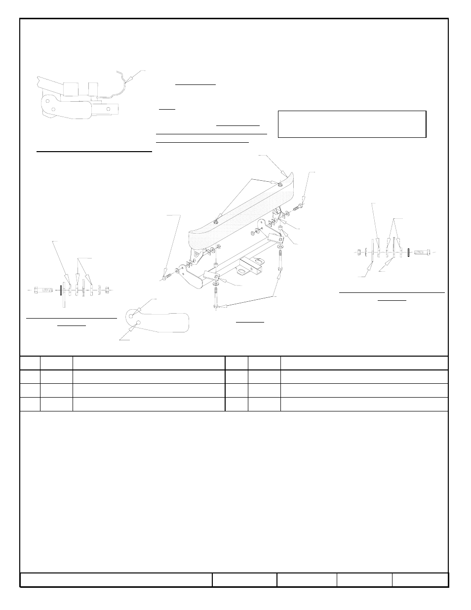
Hitch Shown In Proper Position
Wiring Access Location: SUV1, SUV2
Equipment Required:
Wrenches: (2) 3/4”
Drill Bits: NONE
NOTE TO OWNER: DO NOT TOW
WITH TAILGATE DOWN. DAMAGE
TO TAILGATE MAY ACCURE
1. Raise hitch and loosely secure it to the outside of the drivers side tie down bracket (bolting through the top bracket hole), and inside
of the passenger side tie down bracket (bolt through the bottom bracket hole). See figures 1,2,& 3 for fastener orientation.
2. Swing the hitch rearward aligning the bars and the spacers with the corresponding holes in the impact bar. Install 1/2-13 x 6.50”
bolts and conical toothed washers through the bars and spacers as shown.
3. Tighten all fasteners to the required specifications.
Tighten all other 1/2-13 fasteners with torque wrench to 75 Lb.-Ft.
Rev. C
05/30/06
N24735
Sheet 1 of 3
z
2006 Cequent Towing Products
Xxxx
Qty. (X)
8
WASHER CONICAL
Qty. (4)
4
BOLT – HEX HEAD 1/2-13 X 6.50”
Qty. (2)
7
BLOCK – 1/4 X 1 X 1-1/2
Qty. (6)
3
SPACER
Qty. (2)
6
WASHER FLAT 1/2”
Qty. (2)
2
NUT HEX 1/2-13
Qty. (2)
5
BOLT – HEX HEAD 1/2-13 X 2.50”
Qty. (2)
1
Tighten all 1/2-13 x 6.50 fasteners with torque wrench to 50 Lb.-Ft.
Note: check hitch frequently, making sure all fasteners and ball are properly tightened. If hitch is removed, plug all holes in trunk pan or other body panels to
prevent entry of water and exhaust fumes. A hitch or ball which has been damaged should be removed and replaced. Observe safety precautions when working
beneath a vehicle and wear eye protection. Do not cut access or attachment holes with a torch.
This product complies with safety specifications and requirements for connecting devices and towing systems of the state of New York, V.E.S.C. Regulation V-5
and SAE J684.
2000 LB (908 Kg) Max Gross Trailer Weight
200 LB (90.8 Kg) Max Tongue Weight
Do Not Exceed Lower of Towing Vehicle
Manufacturer’s Rating or
Drawbar Kit:
3590
Fastener Kit: F24735
FASCIA
IMPACT BAR
EXISTING WELD NUT
TIE DOWN
BRACKET
SPACER
BAR
FIGURE 1
OPTIONAL BLOCK
USE AS NEEDED
BLOCKS
BRACKET
TIE DOWN BRACKET
BOLT STACKING PASSENGER SIDE
FIGURE 3
1
2
3
4
5
1
2
3
4
5
647
OPTIONAL BLOCK
USE AS NEEDED
BLOCKS
DRIVER SIDE
BRACKET HOLE
PASSENGER SIDE
BRACKET HOLE
BOLT STACKING DRIVER SIDE
FIGURE 2
Drawbar must be used in the
RISE position only.
Form F206 Rev A 5605