Draw-Tite 24817 SPORTFRAME HITCH User Manual
Installation instructions, Suzuki sx4 crossover, Part numbers
Installation Instructions
Suzuki SX4 Crossover
Part Numbers:
24817
60202
77189
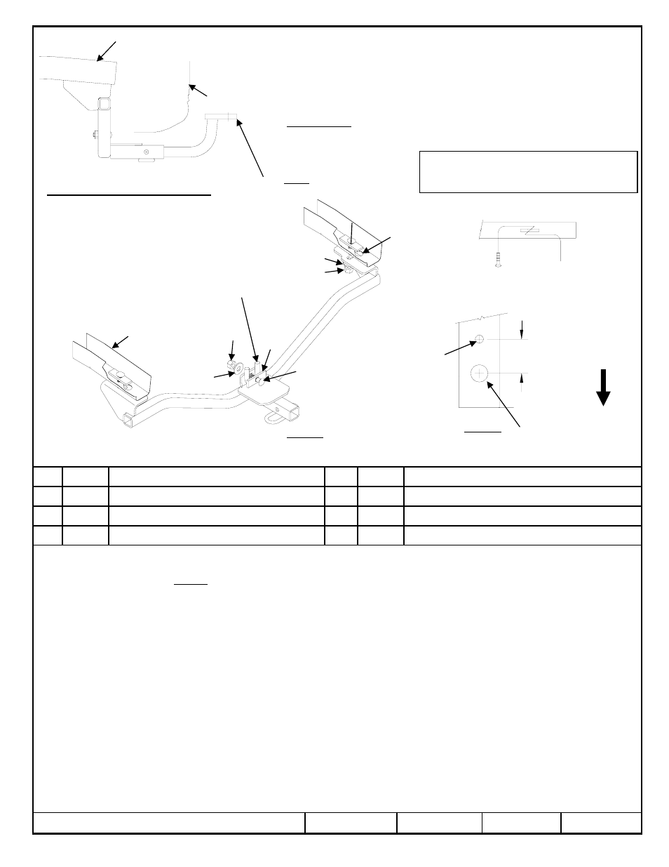
Hitch Shown In Proper Position
Equipment Required: Spray lubricant, Paint,
Pull wire (Provided)
Wrenches: 11/16”, 3/4”
Drill Bits: 1” ” Hole Cut Saw
Fascia
1.
Lower exhaust system at the rubber isolator (3). Spraying a lubricant on the metal hanger rod and the rubber isolator helps
removal.
2.
Drill 1” access hole in bottom of each frame rail. See Figure 2.
3.
Feed pull wires with spacer and bolt into frame rail thru 1” drilled hole and out the attachment holes. Leave pull wire attached
4.
Paint any exposed metal.
5.
Raise hitch into position and attach as shown in Figure 1. Remove pull wires and attach conical washers and nut (be careful
not to push fastener back into frame rail). Hand tighten.
6.
Attach hitch to tow hook as shown in Figure 1. Orient the spacers with respect to the tow hook as shown.
7.
Check to assure hitch is centered on vehicle.
8.
Torque all fasteners to specifications.
9.
Raise exhaust system back into position.
Rev. A
6-18-08
24817N
Sheet 1 of 3
z
2008 Cequent Towing Products
Spacer
Qty. (1)
8
Spacer ( small sq holes)
Qty. (2)
4
Hex nut ½-13
Qty. (1)
7
Hex nut 7/16-14
Qty. (2)
3
Conical washer 1/2
Qty. (1)
6
Conical washer 7/16
Qty. (2)
2
Carriage bolt 1/2-13 X 2.00 Gr5
Qty. (1)
5
Carriage bolt 7/16-14 X 1.50 Gr5
Qty. (2)
1
Tighten all ½ GR5 fasteners with torque wrench to 75 Lb.-Ft. (102 N*M)
Tighten all 7/16 GR5 fasteners with torque wrench to 50 Lb.-Ft. (68 N*M)
Note: check hitch frequently, making sure all fasteners and ball are properly tightened. If hitch is removed, plug all holes in trunk pan or other body panels to prevent
entry of water and exhaust fumes. A hitch or ball which has been damaged should be removed and replaced. Observe safety precautions when working beneath a
vehicle and wear eye protection. Do not cut access or attachment holes with a torch.
This product complies with safety specifications and requirements for connecting devices and towing systems of the state of New York, V.E.S.C. Regulation V-5 and
SAE J684.
Fastener Kit: 24817F
Do Not Exceed Lower of Towing Vehicle
Manufacturer’s Rating or
Wiring Access Location: SUV 1 & 2
2000 LB (908 Kg) Max Gross Trailer Weight
200 LB (90.8 Kg) Max Tongue Weight
Drawbar must be used in
the RISE position only.
Drawbar Kit:
3594
Frame
rail
Kink Pull wire to keep
spacer independent of
bolt
2” [50.8 mm]
1
4
2
3
7
6
8
5
Figure 1
Figure 2
1” dia. – drill
Drilling of Access Holes
Tow Hook
Frame Rail
Note: Fasteners typical both sides
Rearward
of
vehicle
Existing hole
Drilled Hole
Form: F205 Rev A 5-6-05