Draw-Tite 24912 SPORTFRAME HITCH User Manual
Installation instructions, Mazda 3 sedan, Part numbers
Installation Instructions
Mazda 3 sedan
Part Numbers:
24912
60344
77299
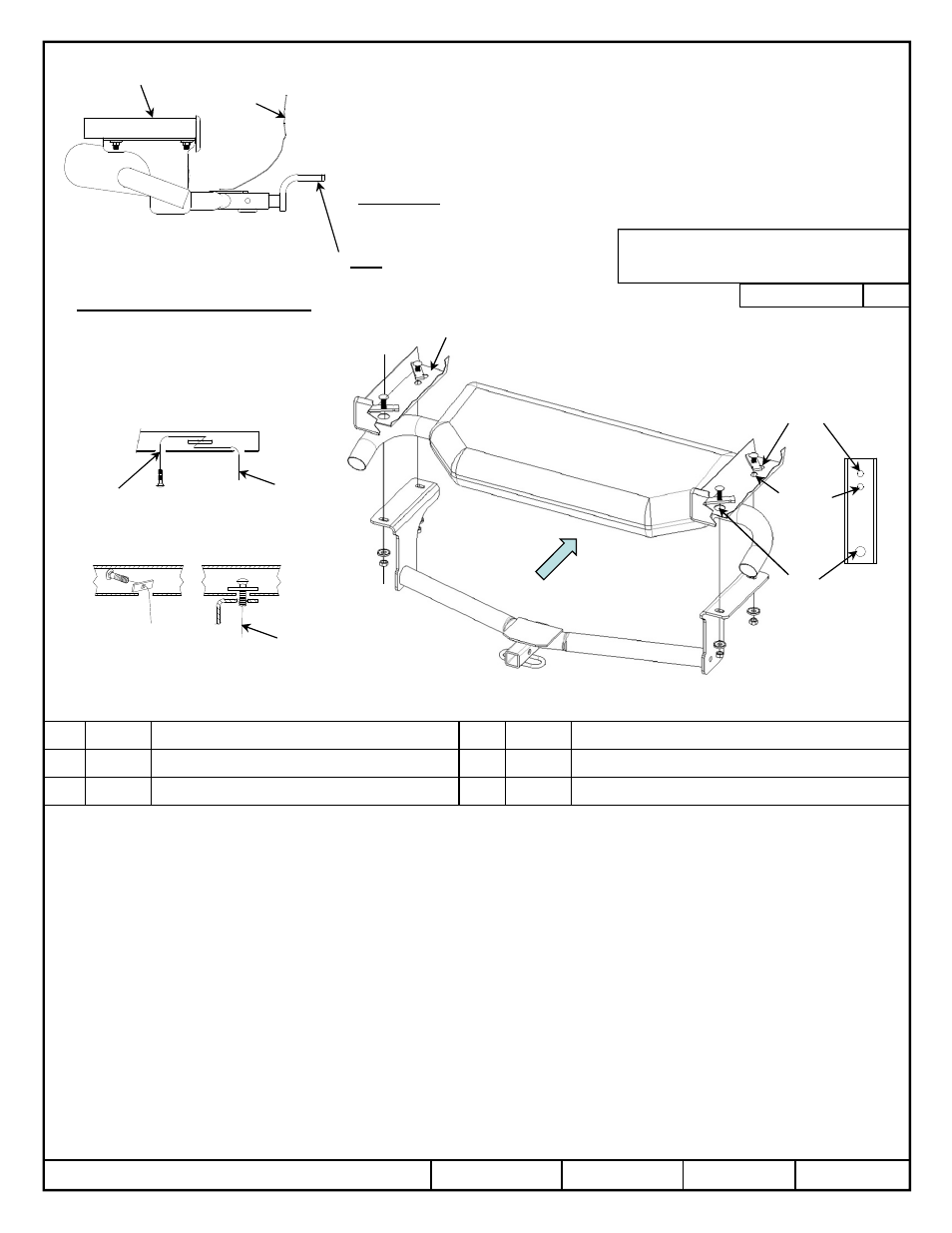
Hitch Shown In Proper Position
Wiring Access Location: PC3, 4
Equipment Required:
Wrenches: 11/16
Drill Bits: None
Frame rail
Printed in Mexico
Note: if additional clearance is needed for installation. Lower exhaust system at the rubber isolators. Spraying a lubricant on the metal hanger rod
and the rubber isolator helps removal.
1.
Raise the hitch into position, feed the pull wires though the adjacent slots on the hitch.
2.
Feed the pull wire into the rearward slot and out the access hole. Attach spacer and carriage bolt to pull wire and feed into frame rail, pull into
position. Both sides. See Figure 2. Leave pull wire attached.
3.
Using the reverse pull wire procedure Figure 3. Feed the pull wire into position both rails. Leave pull wires attached.
4.
Carefully remove pull wires. One at a time place the washer over the pull wire and use it to hold the bolt in place while carefully removing the
pull wire, then attach the hex nut.
5.
Tighten all fasteners to the required torque specification.
z
2013 Cequent Performance Products
Sheet 1 of 3
24912N
11-1-13
Rev. A
1
1
1
1
Qty. (4)
Carriage bolt 7/16-14 X 1.50 GR5
4
4
4
4
Qty. (4)
Hex nut 7/16-14
2
2
2
2
Qty. (4)
Spacer 1/4” X 7/8” X 3”
5
5
5
5
Qty. (4)
Pull wire 7/16”
3
3
3
3
Qty. (4)
Conical tooth washer 7/16”
Tighten all 7/16-14 Gr5 fasteners with torque wrench to 50 Lb.-Ft. (68 N*M)
Note: check hitch frequently, making sure all fasteners and ball are properly tightened. If hitch is removed, plug all holes in trunk pan or other body panels to prevent
entry of water and exhaust fumes. A hitch or ball which has been damaged should be removed and replaced. Observe safety precautions when working beneath a
vehicle and wear eye protection. Do not cut access or attachment holes with a torch.
This product complies with safety specifications and requirements for connecting devices and towing systems of the state of New York, V.E.S.C. Regulation V-5 and
SAE J684.
Do Not Exceed Lower of Towing Vehicle
Manufacturer’s Rating or
Drawbar must be used in the
RISE position only.
Drawbar Kit:
3593
Fastener Kit: 24912F
Form F206 Rev B 9-17-2012
Accessory Rating
A
2000 LB (908 Kg) Max Gross Trailer Weight
200 LB (90.8 Kg) Max Tongue Weight
Note: Fasteners typical
both sides
Access
hole
Kink pull wire to keep
spacer independent of bolt
1
2
3
4
5
Frame rail
Fascia
Access
hole
5
Forward
slot
Rearward
slot
Forward
Reverse pull wire procedure