Draw-Tite 24832 SPORTFRAME HITCH User Manual
Installation instructions, Mazda 6, Part numbers
Drill Bits: 1-1/8 hole saw
24832
Installation Instructions
Mazda 6
Part Numbers:
60222
77205
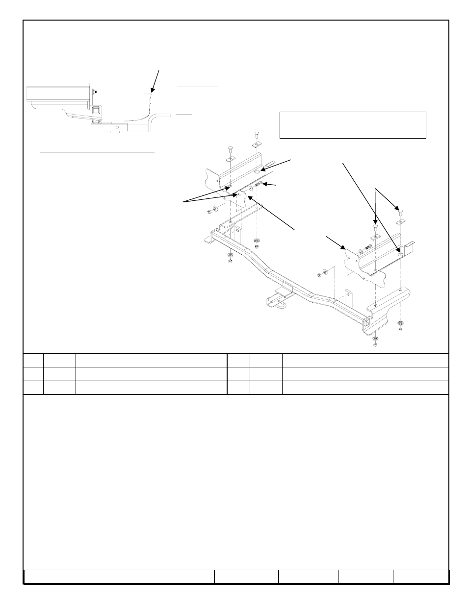
Hitch Shown In Proper Position
Wiring Access Location: PC3, PC4
Equipment Required: Hole Saw, fish wire (provided)
Wrenches: 11/16”
1.
Raise car on ramps or hoist.
2.
Lower exhaust pipe by removing the rubber isolator(s) at the muffler(s) and one isolator near the rear suspension. Support the
exhaust to prevent damage.
NOTE; 6 cylinder models with exhaust trim in rear fascia – remove two black plastic fascia fasteners near the center of the rear panel.
This will allow the fascia to be pulled gently back and down enough to remove tail pipe from exhaust trim.
3.
Raise hitch into place and temporarily install the fasteners in the rear panel. This will locate the hitch.
4.
Using the hitch as a template, mark the forward most hole. Lower the hitch and drill a 1-1/8” access hole in the frame as shown.
5.
Paint any bare metal and fish wire the frame rail fasteners into place through the access hole. Leave the fish wires attached.
6.
Raising hitch into position, routing fish wires thru hitch holes, being careful not to push fasteners back into the frame.
7.
Remove the fish wires, install the remaining fasteners as shown above and tighten to spec.
8.
Raise the exhaust back into position an reconnect to rubber isolators. Reinstall black fascia fasteners if removed.
Rev. A
10-29-08
24832N
Sheet 1 of 3
z
2008 Cequent Towing Products
Washer – flat 7/16”
Qty. (2)
6
Washer – conical 7/16”
Qty. (6)
3
Hex head bolt – 7/16 -14 x 1-1/2” long grade 5
Qty. (2)
5
Block – 1x2x3/16”
Qty. (4)
2
Nut – 7/16 -14
Qty. (6)
4
Carriage bolt – 7/16-14 x 1-1/4” long grade 5
Qty. (4)
1
Tighten all 7/16” fasteners with torque wrench to 50 Lb.-Ft.(68 n*m)
Note: check hitch frequently, making sure all fasteners and ball are properly tightened. If hitch is removed, plug all holes in trunk pan or other body panels to
prevent entry of water and exhaust fumes. A hitch or ball which has been damaged should be removed and replaced. Observe safety precautions when working
beneath a vehicle and wear eye protection. Do not cut access or attachment holes with a torch.
This product complies with safety specifications and requirements for connecting devices and towing systems of the state of New York, V.E.S.C. Regulation V-5
and SAE J684.
2000 LB (908 Kg) Max Gross Trailer Weight
200 LB (90.8 Kg) Max Tongue Weight
Do Not Exceed Lower of Towing Vehicle
Manufacturer’s Rating or
Drawbar must be used in the
RISE position only.
Drawbar Kit:
3592
Fastener Kit: 24832F
1234
56
Fastener are typical
For both sides
34
Drilled access hole
Existing holes
Rear Panel
Fascia
Form F206 Rev A 5605