Draw-Tite 24790 SPORTFRAME HITCH User Manual
Installation instructions, Honda cr-v, Part numbers
Installation Instructions
Honda CR-V
Part Numbers:
60907
24790
77164
Wiring Access Location: SUV3
Equipment Required:
Wrenches: 3/4”
Drill Bits: none
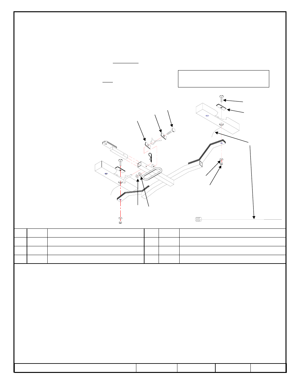
1. Thread bolt leader (3) onto 1 3/4” carriage bolt (1) and insert bolt leader through hole in reinforcing plate (2).
2. Insert carriage bolt, headfirst, followed by reinforcing plate through hole in hole in bottom of frame (refer to “Access to Enclosed Frame” on last page
of instruction sheet) and carefully pull on bolt leader until bolt and reinforcing plate assembly is in position. Repeat for other side
3. Install hitch loosely onto vehicle, being careful not to push bolt assemblies back into frame channels. Remove bolt leaders and install conical washers
(5) and nuts (4). Install 2” carriage bolt (6), along with square hole spacer (7), round hole spacer (8), conical washer (5) & nut (4) through vehicle’s
tie down hook and hitch’s mounting tab in order as shown in illustration.
4. Tighten all bolts, referring to torque table on instruction sheet.
Rev. A
11-09-06
24790N
Sheet 1 of 2
z
2006 Cequent Towing Products
Tighten all 1/2” fasteners with torque wrench to 75 Lb.-Ft. (102 n*m)
Note: check hitch frequently, making sure all fasteners and ball are properly tightened. If hitch is removed, plug all holes in trunk pan or other body panels to
prevent entry of water and exhaust fumes. A hitch or ball which has been damaged should be removed and replaced. Observe safety precautions when working
beneath a vehicle and wear eye protection. Do not cut access or attachment holes with a torch.
This product complies with safety specifications and requirements for connecting devices and towing systems of the state of New York, V.E.S.C. Regulation V-5
and SAE J684.
2000 LB (908 Kg) Max Gross Trailer Weight
200 LB (90.8 Kg) Max Tongue Weight
Do Not Exceed Lower of Towing Vehicle
Manufacturer’s Rating or
Drawbar must be used in the
RISE position only.
Drawbar Kit:
3591
Fastener Kit: 24790F
1
2
3
4
5
6
7
8
4 5
SPACER 1” X 2” X 1/4” (ROUND HOLE)
Qty. (1)
8
NUT 1/2”-13
Qty. (3)
4
SPACER 1” X 2” X 1/4” (SQUARE HOLE)
Qty. (1)
7
BOLT LEADER
Qty. (2)
3
BOLT – CARRIAGE 1/2”-13 X 2” GR 5
Qty. (1)
6
REINFORCEMENT PLATE 1” X 3” X 1/4”
Qty. (2)
2
WASHER – CONICAL TOOTHED
Qty. (3)
5
BOLT – CARRIAGE 1/2”-13 X 1 3/4” GR 5
Qty. (2)
1
Form F206 Rev A 5605