Draw-Tite 24902 SPORTFRAME HITCH User Manual
Installation instructions, Hyundai elantra sedan hyundai elantra coupe, Part numbers
Installation Instructions
Hyundai Elantra Sedan
Hyundai Elantra Coupe
Part Numbers:
24902
60329
77289
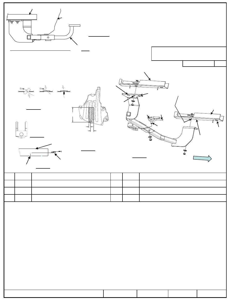
Hitch Shown In Proper Position
Wiring Access Location: PC3, 4
Equipment Required: Pullwires (provided), Lubricant or
Soapy water, Philips screwdriver, Utility Knife, Tape Measure &
Marking Pencil.
Wrenches: M10, 11/16” & 3/4”
Drill Bits: ½”
8-1/8”
Tie down hook
spacer orientation
Caution: due to different manufacturing plants the holes in the frame will vary in position. Drilling may be required
1.
Lower exhaust by removing both rubber isolators from muffler hangers. Spraying a lubricant or soapy water on the metal hanger rod and the rubber isolator
helps removal
2.
Remove the appearance panel on driver’s side if present. Obtain owners permission to trim or return to owner. See Figure 3
3.
Remove rubber plug in frame rails, loosen the heat shield if needed.
4.
On North American built vehicles install 7/16 carriage bolt and spacer using reverse pull wire procedure leaving pull wire attached. See Figure 4 Identify if
drilling is required - Asia built sedans enlarge holes in frame rail. Install 7/16 carriage bolt and spacer through access holes, leave pull wire attached. On the
Coupe enlarge holes in frame rail. Install 7/16 carriage bolt and spacer through access holes, leave pull wire attached. See Figure 5
5.
Place 1/2” carriage bolt and spacer on tie down hook orientation as shown. See Figure 2
6.
Raise passenger side of hitch over exhaust, and loosely install center attachment, feed pull wires through rearward slot on sedan and forward slot on coupes.
Install remaining fasteners as shown. See Figure 1
7.
Tighten all fasteners to the required torque specification.
8.
Reinstall the vehicle exhaust. Re-install appearance panel if removed and trimmed.
z
2012 Cequent Performance Products, Inc
Sheet 1 of 3
24902N
11-13-12
Rev. A
j
Qty. (1)
Carriage bolt ½-13 X 1.75 Gr. 5
n
Qty. (2)
Carriage bolt 7/16-14 X 1.50 Gr5
k
Qty. (1)
Spacer .25 X 1.50 X 3.0
o
Qty. (2)
Spacer .25 X .88 X 3.00
l
Qty. (1)
Conical washer ½”
p
Qty. (2)
Conical washer 7/16”
m
Qty. (1)
Hex nut ½-13
q
Qty. (2)
Hex nut 7/16-14
Note: check hitch frequently, making sure all fasteners and ball are properly tightened. If hitch is removed, plug all holes in trunk pan or other body panels to prevent
entry of water and exhaust fumes. A hitch or ball which has been damaged should be removed and replaced. Observe safety precautions when working beneath a
vehicle and wear eye protection. Do not cut access or attachment holes with a torch.
This product complies with safety specifications and requirements for connecting devices and towing systems of the state of New York, V.E.S.C. Regulation V-5 and
SAE J684.
Do Not Exceed Lower of Towing Vehicle
Manufacturer’s Rating or
Drawbar must be used in the
RISE position only.
Drawbar Kit:
3594
Fastener Kit: 24902F
Form F206 Rev B 9-17-2012
Accessory Rating
B
2000 LB (908 Kg) Max Gross Trailer Weight
200 LB (90.8 Kg) Max Tongue Weight
Tighten all 7/16” Gr5 fasteners with torque wrench to50 Lb.-Ft. (68 N*M)
Tighten all 1/2 Gr5 fasteners with torque wrench to 75 Lb.-Ft. (102 N*M)
A. Insert bolt and
Block into frame B. Align block on
access hole
C. Pull bolt thru
block
Figure 4
Reverse pullwire procedure
j
1”
1-3/4”
k
l
m
n
o
q
p
Note: Fasteners typical
both sides
Access
hole
Coupe – enlarge
hole with ½” drill
Clearance
hole for
stud
Enlarge hole with ½”
drill as required
Area to trim on
appearance panel
Coupe –
mounting holes
Sedan -
mounting
holes
Tie
down
hook
Example of
Asia made
frame rail
Frame rail
Fascia
Forward
Figure 1
Figure 2
Figure 3
Access hole
Kink pull wire to keep block
independent of bolt
Bumper
Figure 5
Example of
North American
made frame rail