Draw-Tite 24857 SPORTFRAME HITCH User Manual
Installation instructions, Jk l m n, Bmw 328 sedan
Installation Instructions
BMW 328 Sedan
Part Numbers:
24857
60273
77231
24863
U-Haul
Hitch Shown In Proper Position
Wiring Access Location: P3, 4
Equipment Required:
Wrenches: 8mm, 10mm, 18mm,
& 3/4
Xxxx
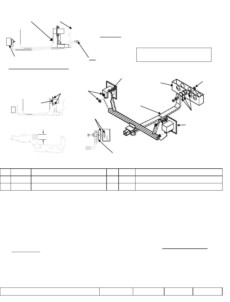
Fig 1.
1.
Remove both appearance panels, (10) 8mm, (4) 10mm retain for reinstallation.
2.
Remove (4) existing M12 flange nuts located on vehicle end panel as shown Fig 1. Spraying with a lubricant will assist the
removal. Retain for re-installion. Wash lubricant off studs, if used.
3.
Place (3) flat washers on each stud .
4.
Raise hitch into position by rotating hitch behind fascia as shown in Fig 2., reinstall existing flange nuts removed in step 2, finger
tight only.
5.
Determine numbers of spacer needed between hitch bar and vehicle frame cross member (minimum of 1).
6.
Using pullwire insert carriage bolt and (1) spacer into vehicle frame cross member, thread pull wire through spacer/s and hitch bar
as shown Fig 4. Remove pull wire and install conical washer and hex nut onto carriage bolt.
7.
Tighten fasteners to torque specified.
8.
Reinstall appearance panel on passenger side.
9.
Drivers side appearance panel will need to be trimmed (see Fig 3) or returned to owner. Obtain owners permission
before trimming.
z
2010, 2011, 2012 Cequent Performance Products
Sheet 1 of 3
24857N
1-9-12
Rev. C
j
Qty. (12)
Flat washers7/16”
m
Qty. (1)
Conical washer 1/2”
k
Qty. (1)
Carriage bolt ½-13 X 2.50 GR5
n
Qty. (1)
Hex nut
l
Qty. (3)
Spacers
o
Qty. (1)
Pullwire 1/2”
Tighten all 12mm fasteners with torque wrench to 62 Lb.-Ft. (84 N*M)
Tighten all ½-13 GR 5 fasteners with torque wrench to 75 Lb.-Ft. (102 N*M)
Note: check hitch frequently, making sure all fasteners and ball are properly tightened. If hitch is removed, plug all holes in trunk pan or other body panels to
prevent entry of water and exhaust fumes. A hitch or ball which has been damaged should be removed and replaced. Observe safety precautions when working
beneath a vehicle and wear eye protection. Do not cut access or attachment holes with a torch.
This product complies with safety specifications and requirements for connecting devices and towing systems of the state of New York, V.E.S.C. Regulation V-5
and SAE J684.
Do Not Exceed Lower of Towing Vehicle
Manufacturer’s Rating or
Drawbar must be used in the
Rise position only.
Drawbar Kit:
3593
Fastener Kit: 24857F
Form F206 Rev A 5605
2000 LB (908 Kg) Max Gross Trailer Weight
200 LB (90.8 Kg) Max Tongue Weight
Trunk pan
Fascia
2.50 / 64mm
Driver’s side
Appearance panel trim
Rotate hitch behind fascia
j
k
l
m
n
Existing
flange
nuts
Vehicle frame
cross member
Vehicle end panel
Vehicle frame
cross member
Fig 2.
Fig 3.
Fig 4.
Pullwire example
Spacer to be
removed if
needed
Studs
Vehicle end
panel
Orient
spacers as
shown
Hitch
bar.