Draw-Tite 24872 SPORTFRAME HITCH User Manual
Installation instructions, Ford focus, Part numbers
Installation Instructions
Ford Focus
(All except ST model)
Part Numbers:
24872
60290
77256
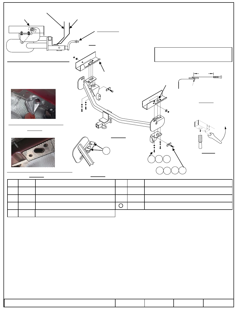
Hitch Shown In Proper Position
Wiring Access Location: Sedan PC3, 4, 5-Door PC1, 2
Equipment Required: Tin Snips
Wrenches: 13mm, 11/16
1.
Lower exhaust system by removing (2) M8 bolts holding exhaust hanger and return bolts to vehicle owner, both sides – See figure 2.
2.
Trim heat shield in area where hitch side bracket mounts to the bottom of the frame – See figure 3.
3.
Cut plastic isolator strips in half and apply the two halves of each strip to bottom of hitch side brackets between slot and large access hole – See figure 5.
Note: The isolators strips go between the exhaust hanger and side bracket.
4.
Raise hitch into position and re-install exhaust hangers using the M8-1.25 x 40mm bolts, lock washers, and flat washers provided with hitch.
5.
Using pull wire, install block and 7/16 carriage bolt through access hole in hitch and bottom of frame and through hole on side of frame.
Note: It is much easier if bolt and spacer are not engaged while inserting them into frame -See Figure 4
6.
Install conical toothed washer and hex nut onto carriage bolt, both sides.
7.
Torque all fasteners to specifications.
Tighten all 7/16-14 GR5 fasteners with torque wrench to 50 Lb.-Ft. (68 N*M) Tighten all M8-1.25 CL10.9 fasteners with torque wrench to 27 Lb.-Ft. (37 N*M)
© 2011, 2013 Cequent Performance Products, Inc
– Printed in México
Sheet 1 of 3
24872N
10-04-13
Rev. C
j
Qty. (2)
Carriage bolt 7/16-14 X 1.50 GR5
o
Qty. (4)
5/16 Flat Washer
k
Qty. (2)
Block, ¼ x 7/8 x 3.00
p
Qty. (4)
5/16 Lock Washer
l
Qty. (2)
7/16 Conical washer
q
Qty. (2)
Pull wire 7/16
m
Qty. (2)
Hex nut 7/16-14
Qty. (2)
Plastic Isolators
Note: check hitch frequently, making sure all fasteners and ball are properly tightened. If hitch is removed, plug all holes in trunk pan or other body panels to prevent
entry of water and exhaust fumes. A hitch or ball which has been damaged should be removed and replaced. Observe safety precautions when working beneath a
vehicle and wear eye protection. Do not cut access or attachment holes with a torch.
This product complies with safety specifications and requirements for connecting devices and towing systems of the state of New York, V.E.S.C. Regulation V-5 and
SAE J684.
Do Not Exceed Lower of Towing Vehicle
Manufacturer’s Rating or
Drawbar must be used in the
Rise position only.
Drawbar Kit:
3593
Fastener Kit: 24872F
Form F206 Rev A 5605
Figure 4
Kink pull wire to keep
block independent of bolt
Figure 1
Access hole
Fasteners typical
both sides
Frame rail
Frame rail
Fascia – 5 Door
2000 LB (908 Kg) Max Gross Trailer Weight
200 LB (90.8 Kg) Max Tongue Weight
Trim heat shield in area shown – Both sides
Apply plastic isolator strips
To bottom of hitch side bracket
Both sides
Remove exhaust hanger – Both sides
1 2 3 4
n
Qty. (4)
Bolt, M8-1.25 x 40mm CL10.9
9
9
5 6 7
Figure 3
Figure 2
3”
Fascia – Sedan
Figure 5
Metal File
Oblong access hole
Figure 6
Wrench
NOTE: Check to see if spacer and carriage bolt will fit through access hole, if not modify hole to accept hardware, the illustration, see figure 6, shows two ways of achieving this, the first is
using a file, the second is by inserting a wrench or prying as shown. Enlarge hole just enough to get hardware through.