Installation instructions, Toyota camry, Toyota avalon – Draw-Tite 36514 FRAME HITCH User Manual
Page 2: Toyota avalon install, Part numbers
Installation Instructions
Toyota Camry
page 1
Toyota Avalon
page 2
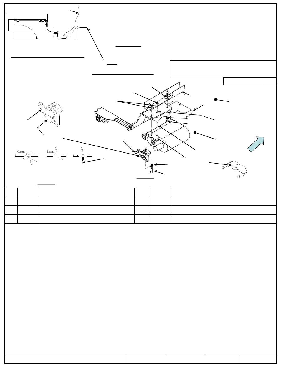
Part Numbers:
Hitch Shown In Proper Position
Wiring Access Location: PC3 & 4
Equipment Required: Strap or bungee
cords to support exhaust
Wrenches: 10mm, 12mm, 14mm,
17mm, 6” socket extension, 11/16”
Drill Bits: ¼”, 1”, ½”
1.
Remove appearance panel and return panel to owner.
2.
Lower exhaust by removing two bolts at the end panel and two bolts on the frame rail exhaust hanger bracket each side. End panel bolts to be
reinstalled.
3.
Support the exhaust to prevent damage using straps, bungee cords or other means. Remove 1
st
rubber isolator bracket on the forward
passenger side of the exhaust and the next 2
nd
forward rubber isolator bracket.
4.
Remove heat shields.
5.
Raise (slide) hitch into position over exhaust pipes and temporarily install M10 hex bolts for support. Exhaust hanger bracket not necessary at
this step.
6.
Using the hitch as a template mark and center punch the (1) holes on both sides. Drill ¼” pilot hole both sides.
7.
Lower hitch and drill 1” hole in frame rail. Mark and drill heat shield for the 7/16 carriage bolt using the frame rail as template. Set aside for later
install.
8.
Insert carriage bolt and spacer into the frame as shown leaving pull wire attached. See Figure 2.
9.
Raise hitch into position threading the pullwire through the bracket. Install at least one M10 bolts as shown both sides.
10. Remove pullwire and install conical washers and nuts on both side. Center hitch and
Torque 7/16” fasteners to required specification. Install
heat shield.
11. Install the 1
st
& 2
nd
forward rubber isolator brackets.
12. Remove M10 bolts and install the exhaust hanger brackets thru the forward weld nut both sides (item 1).
13. Install vehicle support bracket re-using the existing end panel bolts and (item 1) remaining M10 bolts.
14. Tighten all fasteners to the required torque specification.
©
2011, 2013 Cequent Performance Products, Inc
Sheet 2 of 6
36514N
4-25-13
Rev. D
j
Qty. (4)
Hex bolt M10 X 1.25 X 40 CL8.8
n
Qty. (2)
Conical Washer 7/16”
k
Qty. (4)
Conical washer 3/8”
o
Qty. (2)
Hex nut 7/16-14
l
Qty. (2)
Carriage bolt 7/16-14 X 1.5 GR5
p
Qty. (2)
Pullwire 7/16
m
Qty. (2)
Spacer
q
Qty. (2)
Hex bolt M6 X 1.0 X 40
Note: check hitch frequently, making sure all fasteners and ball are properly tightened. If hitch is removed, plug all holes in trunk pan or other body panels to prevent
entry of water and exhaust fumes. A hitch or ball which has been damaged should be removed and replaced. Observe safety precautions when working beneath a vehicle
and wear eye protection. Do not cut access or attachment holes with a torch.
This product complies with safety specifications and requirements for connecting devices and towing systems of the state of New York, V.E.S.C. Regulation V-5 and
SAE J684.
Do Not Exceed Lower of Towing Vehicle
Manufacturer’s Rating or
Drawbar must be used in the
RISE position only.
Drawbar Kit:
36071
Fastener Kit: 36514F
Form F206 Rev A 5605
36514
90079
06139
3500 LB (1589 Kg) Max Gross Trailer Weight
300 LB (136 Kg) Max Tongue Weight
Note: Fasteners typical both sides of hitch.
Tighten all M10 CL8.8 fasteners with torque wrench to 38 Lb.-Ft. (52 N*M)
Tighten all 7/16 GR5 fasteners with torque wrench to 50 Lb.-Ft. (68 N*M)
Figure 1
Fascia
p
A. Insert bolt and
Block into frame
B. Align block
on access hole
C. Pull bolt
thru block
Figure 2
Accessory Rating
B
Toyota Avalon install
Side
specific
Toyota Avalon view
l
m
1” hole to be
drilled both sides
Forward weld nut
Existing M10
weld nuts
End panel
bolts
Frame rail
Heat
shield
2
nd
Forward rubber
isolator bracket
location
Drill ½” to ¾” hole
n
o
1
st
Forward rubber
isolator bracket
location
q
Forward
Exhaust hanger
bracket
j
k
Vehicle
support
bracket