Draw-Tite 36530 FRAME HITCH User Manual
Installation instructions, Part numbers
Installation Instructions
Lexus ES350 & 300h
Part Numbers:
36530
90227
06154
36921
U-Haul
Hitch Shown In Proper Position
Wiring Access Location: PC3, 4
Equipment Required: Pull wires (provided), Tin snips, lubricant or
soapy water
Wrenches: 10mm, 12mm, 13mm,14mm, 17mm,
11-/16”, 3/4”, and small screwdriver
Drill Bits: ¼” & 1” drill
Frame rail
Do Not Exceed Lower of Towing Vehicle
Manufacturer’s Rating or
Drawbar must be used in the
RISE position only.
Drawbar Kit:
36071
Fastener Kit: 36530F
Accessory Rating
B
3500 LB (1589 Kg) Max Gross Trailer Weight
300 LB (136 Kg) Max Tongue Weight
A. Insert bolt and
Block into frame
B. Align block on
access hole
Pull wire Procedure
C. Pull bolt thru
block
9
9
9
9
6
6
6
6
5
5
5
5
1
1
1
12
2
2
2
7
7
7
7
8
8
8
8
Figure 3
Lexus ES300h only
Figure 2
Vehicle exhaust
hanger bracket
Drill the forward
holes. Using
hitch as template
2
2
2
2
Frame rail
Fascia
*
3
3
3
3
Heat shield
access holes
Figure 1
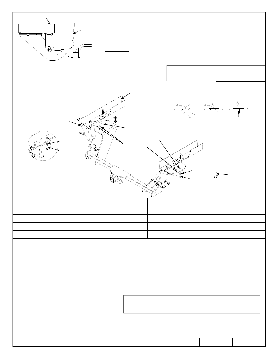
1.
Remove, under vehicle, appearance panel on the ES300h only and return to owner.
2.
Lower exhaust system at the rubber isolator (4 places). Spraying a lubricant on the metal hanger rod and the rubber isolator helps with removal. Be sure to
Support the exhaust system. Lower the exhaust further by removing the hanger behind the passenger side muffler and the next hanger using a 12mm socket.
3.
Loosen the vehicles exhaust, at the hanger brackets, using a 14mm socket (3 places) each side.
4.
Remove the heat shield/shields.
5.
Temporarily raise the hitch into position, over the exhaust, and loosely install the ½” fasteners to the vehicle hanger brackets. Use the additional ½ flat washer
(*3) as needed due to vehicle variance. Push the forward brackets into place, against the bottom of vehicle frame. If forward hole (both sides) do not align with an
existing vehicle frame hole then mark and center punch the hole location to be drilled using the hitch as a template.
6.
Lower hitch and drill 1/4” pilot hole and 1” access hole as needed
(caution wires, fuel lines, etc..).
Mark and drill the heat shield for the 7/16 carriage bolt.
7.
Feed (items 5 & 6) into the frame rail using the reverse pull wire procedure. Figure 2. Leave pull wires attach.
8.
Raise hitch back into position and loosely install the 1/2 fasteners to the vehicle hanger brackets, feed the pull wires through the bracket and install remaining fasteners.
9.
Reinstall the heat shield.
10.
Tighten all fasteners to the required torque specification.
z
2013 Cequent Performance Products, Inc
Sheet 1 of 3
36530N
4-11-13
Rev. A
1
1
1
1
Qty. (2)
Hex bolt ½-13 X 1.75 GR5
6
6
6
6
Qty. (2)
Spacer
2
2
2
2
Qty. (2)
Conical washer 1/2”
7
7
7
7
Qty. (2)
Conical washer 7/16”
3
3
3
3
Qty. (4)
Flat washer 1/2” * (2) optional
8
8
8
8
Qty. (2)
Hex nut 7/16-14
4
4
4
4
Qty. (2)
Hex nut 1/2”
9
9
9
9
Qty. (2)
Hex bolt M6 X 1.00 X 16mm
5
5
5
5
Qty. (2)
Carriage bolt 7/16-14 X 1.50 GR5
Qty. (1)
Hex bolt M10 X 1.25 X 30mm
Note: check hitch frequently, making sure all fasteners and ball are properly tightened. If hitch is removed, plug all holes in trunk pan or other body panels to prevent
entry of water and exhaust fumes. A hitch or ball which has been damaged should be removed and replaced. Observe safety precautions when working beneath a
vehicle and wear eye protection. Do not cut access or attachment holes with a torch.
This product complies with safety specifications and requirements for connecting devices and towing systems of the state of New York, V.E.S.C. Regulation V-5 and
SAE J684.
Form F206 Rev B 9-17-2012
2
2
2
2
3
3
3
3
3
3
3
34
4
4
4
8
8
8
8
Tighten all M10 CL8.8 fasteners with torque wrench to 38 Lb.-Ft. (52 N*M)
Tighten all 7/16 GR 5 fasteners with torque wrench to 50 Lb.-Ft. (68 N*M)
Tighten all ½ GR5 fasteners with torque wrench to 75 Lb.-Ft. (102 N*M)
* ½” flat washer to be
used as needed
*
Item 9 – M6 bolt for
heat shield