Draw-Tite 36492 FRAME HITCH User Manual
Installation instructions, Ford taurus, Part numbers
Installation Instructions
Ford Taurus
All-Including SHO
Part Numbers:
36492
90075
06121
Vehicle
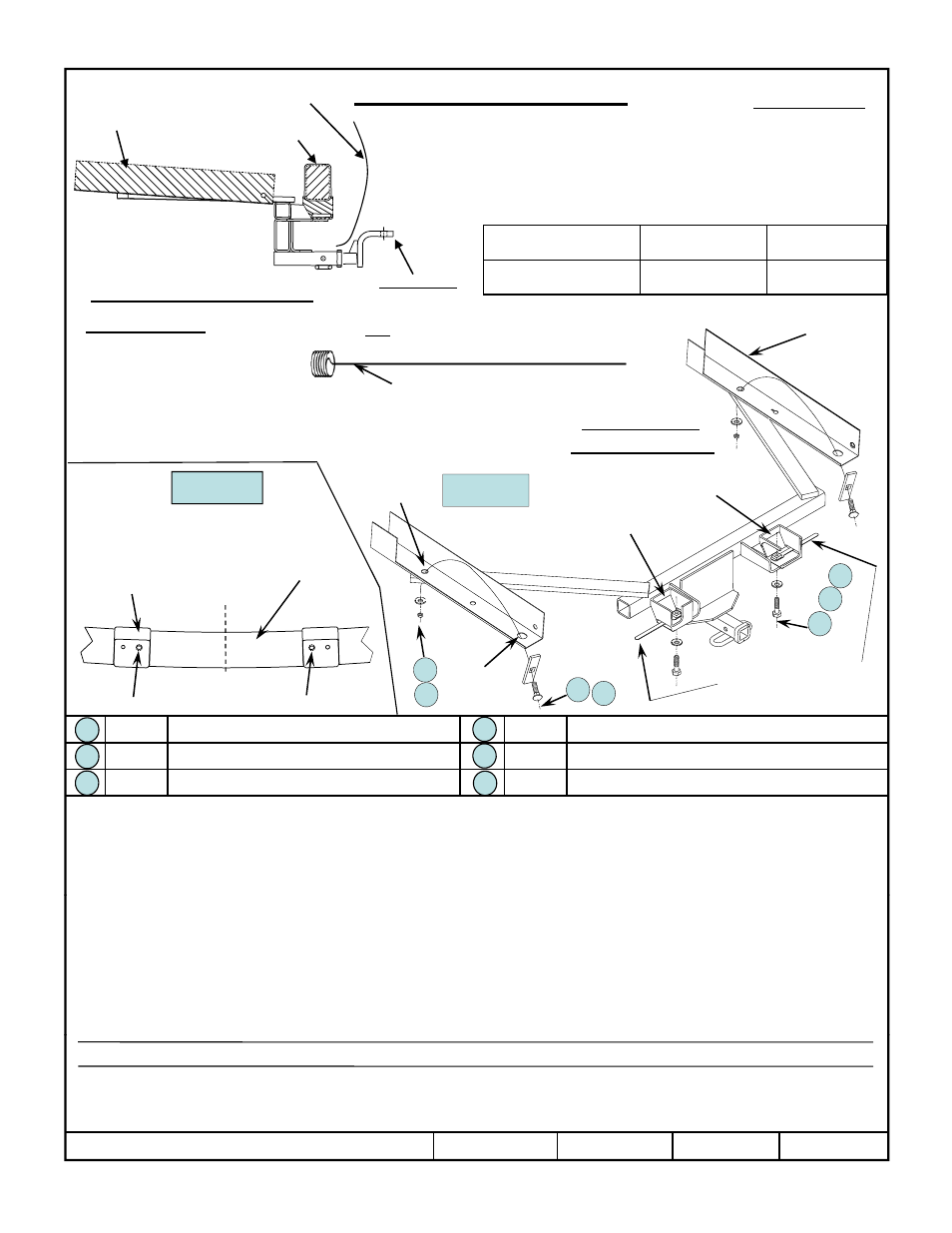
Frame
Bumper
Bumper
Fascia
Hitch Shown In Proper Position
Equipment Required:
Vehicle
Do Not Exceed Lower of Towing Vehicle Manufacturer’s Rating or
Hitch type
Max Gross
Trailer WT (LB)
Max Tongue
WT (LB)
Weight Carrying
Ball Mount
3500 (1589 Kg)
300 (136 Kg)
Wiring Access Location: PC3 , PC4
Drawbar must be used in the
Rise position only.
Drawbar Kit:
36071
Wrenches: 18mm, 3/4”, 7/8”
Drill Bits: 1/2”
Ve c e
Frame rail.
Cut-away to
show detail
Fastener Kit: 36492F
Lower exhaust system, (not shown),
for ease of installation,
Fasteners Typical
Both Sides of Vehicle
E i ti
Other items: Spray lubricant
Magnified view of a Bolt Leader for Fish-wiring
Bumper pods on bottom of
bumper, (cut-away to show
detail). Bumper not shown.
Existing
hole
Figure 1.
Figure 2.
Bumper
Bumper
pods
Bottom view of bumper showing detail for
enlarging existing holes in bumper pods.
Centerline
of vehicle
3
6
Qty. (2)
Carriage Bolt, 1/2”-13 X 1-3/4” Gr. 5
Qty. (2)
Hex Nut, 1/2”-13
Qty (2)
Carriage Block 1/4” X 1” X 3”
Qty (2)
Hex Bolt 1/2”-13 X 1-1/4” Gr 5
Slide handle nuts through
slots on outside of pods.
1
2
Access
hole
Enlarge these existing holes.
5
4
3
4
2
1
5
1.
Remove plastic push rivets holding bumper fascia straps to bumper pods both sides. Bend fascia straps down. Drill out existing holes in
bottom of bumper pods as shown in Figure 1 above. Be sure to drill out the elongated holes toward the center of vehicle on both bumper
pods.
2.
Temporarily lower exhaust system by removing the rubber isolators off of the muffler hanger on vehicle frame and below rear axle. On dual
muffler remove Passenger side hanger bracket. It helps to spray a lubricant on rubber isolators to aid in removal.
3.
Fish-wire 1/2”Carriage bolts and blocks through large access holes in bottom of vehicle frame and down through 3/4” holes in bottom of
vehicle frame as shown in Figure 2 above Typical both sides of vehicle
Qty. (2)
Carriage Block, 1/4 X 1 X 3
Qty. (2)
Hex Bolt, 1/2 -13 X 1-1/4 Gr.5
Qty. (4)
Conical Toothed Washer, 1/2”
Qty. (2)
*Handle-Nut, 1/2”-13 (See torque specs below)
2
3
6
5
vehicle frame as shown in Figure 2 above. Typical both sides of vehicle.
4.
Raise hitch into position over the muffler(s) and exhaust pipe(s) aligning the holes in the hitch over the bolts previously installed in Step 3.
Be careful not to push bolts back up into frame. Loosely install the 1/2” conical toothed washers & nuts.
5.
Holding hitch up against bottom of bumper pods align holes in hitch with previously drilled out holes in bumper pods from Step 1. If
necessary run drill bit up through hitch and bumper to align.
6.
Install 1/2” hex bolts & conical washers up through hitch and through bumper brackets into handle-nuts as shown above.
7.
Center hitch on vehicle and tighten fasteners to specifications below.
8.
Raise exhaust system back into position, re-attaching hanger bracket if removed and rubber isolators including under axle. Also re-attach
plastic bumper fascia straps and rivets removed in Step 1.
p
p
p
S p
Tighten 1/2”-13 Gr.5 bolts with torque wrench to 75 Lb.-Ft. (102 N*M) *Tighten 1/2”-13 Gr. 5 bolts into handle-nuts to 50 Lb.-Ft. (68 N*M).
z
2009 Cequent Towing Products
Sheet 1 of 3
36492N
7-31-09
Rev. A
Note: check hitch frequently, making sure all fasteners and ball are properly tightened. If hitch is removed, plug all holes in trunk pan or other body panels to
prevent entry of water and exhaust fumes. A hitch or ball which has been damaged should be removed and replaced. Observe safety precautions when working
beneath a vehicle and wear eye protection. Do not cut access or attachment holes with a torch.
This product complies with safety specifications and requirements for connecting devices and towing systems of the state of New York, V.E.S.C. Regulation V-5
and SAE J684.
Form: F205 Rev A 5-6-05