Draw-Tite 36541 FRAME HITCH User Manual
Installation instructions, Acura rlx, Part numbers
Installation Instructions
Acura RLX
Fascia trimming required.
Part Numbers:
36541
90235
06161
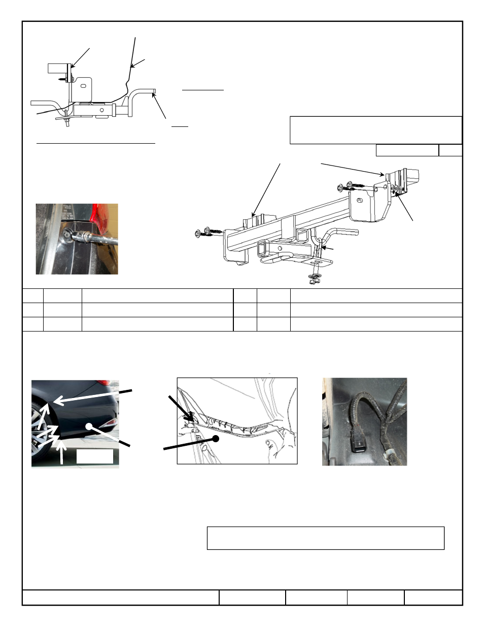
Hitch Shown In Proper Position
Wiring Access Location: PC3 & 4
Equipment Required: Utility knife, tape measure & marking pencil
Phillips screwdriver, small flat screwdriver
Wrenches: 10mm, 12mm, 13mm, 11/16”
Drill Bits: None
Figure 2
1
z
2014 Cequent Performance Products, Inc
Sheet 1 of 6
36541N
2-14-14
Rev. A
1
1
1
1
Qty. (4)
Hex bolt M 8 X 1.25 X 55mm CL9.8
4
4
4
4
Qty. (2)
Conical washer 3/8”
2
2
2
2
Qty. (8)
Washer flat 5/16”
5
5
5
5
Qty. (2)
Hex nut 3/8-16”
3
3
3
3
Qty. (1)
U-Bolt 3/8-16 GR5
Tighten all M8 CL 9.8 fasteners with torque wrench to 25 Lb.-Ft. (34 N*M)
Tighten all 3/8-16 GR 5 fasteners with torque wrench to 30 Lb.-Ft. (41 N*M)
Note: check hitch frequently, making sure all fasteners and ball are properly tightened. If hitch is removed, plug all holes in trunk pan or other body panels to prevent
entry of water and exhaust fumes. A hitch or ball which has been damaged should be removed and replaced. Observe safety precautions when working beneath a
vehicle and wear eye protection. Do not cut access or attachment holes with a torch.
This product complies with safety specifications and requirements for connecting devices and towing systems of the state of New York, V.E.S.C. Regulation V-5 and
SAE J684.
Do Not Exceed Lower of Towing Vehicle
Manufacturer’s Rating or
Drawbar must be used in the
RISE position only.
Drawbar Kit:
36071
Fastener Kit: 36541F
Form F206 Rev B 9-17-2012
Accessory Rating
B
Printed in Mexico
3500 LB (1589 Kg) Max Gross Trailer Weight
300 LB (136 Kg) Max Tongue Weight
3
4
5
2
End panel
Fascia
Fasteners typical both sides
Figure 1
See next page for continuing instructions
Note: Obtain owners permission before installing
1. Open trunk and remove the bolts near the tail lights, remove small plastic caps with small screwdriver then using a 10mm socket remove the
bolts. Keep for re-installation. See Figure 2
2. Remove the (4) plastic rivets that fasten the fascia tabs to the vehicle. Note: Remove the center of the rivet with a flat screwdriver. Keep for
re-installation.
3. Remove (4) screws at the fascia to the wheel well. Both sides. One on the bottom of fascia two behind the wheel, and one straight up behind
the bumper fascia to side panel connection points. See Figure 3. Due to vehicle variation, alternate or additional attachments might be
unaccounted for, assure all fasteners are removed before removing fascia.
4. Mark the center line of the fascia with tape using the tie down hook as the center of the vehicle.
5. Carefully remove fascia from vehicle, starting at the rear wheel well and working the way toward the rear of the vehicle. Note: vehicle with
sensors have additional wiring attached to the rear fascia. Disconnect the wiring at the connector attached to the end panel, carefully set the
fascia cover aside. See Figure 4
Figure 4
End panel
starting at
the rear
wheel well
Figure 3
Bumper
fascia