Draw-Tite 36317 FRAME HITCH User Manual
Installation instructions, Chevrolet malibu – sedan only, Part numbers
Installation Instructions
Chevrolet Malibu – Sedan Only*
Part Numbers:
06988
36317
90132
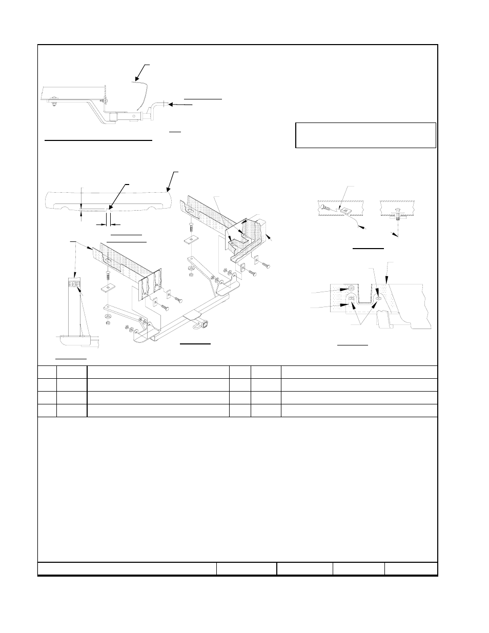
Hitch Shown In Proper Position
Wiring Access Location: PC3, PC4
Equipment Required: Chisel, Hammer, Cut-off Wheel, Pull Wire (provided)
Wrenches: 13mm, 11/16, 3/4
Drill Bits: 3/8”
1.
Lower muffler by removing the two (2) rearmost exhaust hangers.
2.
Remove the bottom four (4) 8mm bumper bolts from the end panel.
Note: Do not loosen or remove the top bumper bolt.
3.
Remove existing weldnut from end panel on the inboard side of frame rail (see figure 2).
4.
If necessary, enlarge existing holes in end panel using a 3/8” drill.
5.
Raise hitch into position, aligning slots in hitch with holes in vehicle end panel.
Note: The upright bracket goes on the forward side of the end panel.
Note: SS Model requires fascia trim obtain vehicle owner’s approval. See Figure 5.
6.
Loosely install the 3/8” carriage bolts and blocks, conical washers and hex nuts as shown in figure 1.
7.
Fishwire 1/2” carriage bolt and block thru large slot in bottom of frame rail as shown. Orient blocks as shown (See Figure 4). Attach conical
washers and nuts as shown.
Note: Keep bolt and block separate while inserting fasteners thru slot (see figure 3).
8.
Tighten fasteners to specified torque ratings as follows:
Tighten all 3/8-16 GR5 fasteners with torque wrench to 30 lb.-ft. (41 N*M)
Tighten all ½-13 GR5 fasteners with torque wrench to 75 lb.-ft. (102 N*M)
9.
Reinstall exhaust hangers removed in step 1.
Rev. B
7-25-06
N36317
Sheet 1 of 3
z
2003, 2006 Cequent Towing Products
Hex Nut ½-13
Qty. (2)
8
Hex Nut 3/8-16
Qty. (4)
4
Conical Washer ½”
Qty. (2)
7
Conical Washer 3/8”
Qty. (4)
3
Block ¼ x 1-1/2 x 3
Qty. (2)
6
Block 3/16 x 1-1/8 x 2
Qty. (4)
2
Carriage Bolt ½-13 x 2.00
Qty. (2)
5
Carriage Bolt 3/8-16 x 1.50
Qty. (4)
1
Note: check hitch frequently, making sure all fasteners and ball are properly tightened. If hitch is removed, plug all holes in trunk pan or other body panels to prevent
entry of water and exhaust fumes. A hitch or ball which has been damaged should be removed and replaced. Observe safety precautions when working beneath a
vehicle and wear eye protection. Do not cut access or attachment holes with a torch.
This product complies with safety specifications and requirements for connecting devices and towing systems of the state of New York, V.E.S.C. Regulation V-5 and
SAE J684.
3500 LB (1 589 Kg) Max Gross Trailer Weight
300 LB ( 136 Kg) Max Tongue Weight
Do Not Exceed Lower of Towing Vehicle
Manufacturer’s Rating or
Drawbar must be used in the
Rise position only.
Drawbar Kit:
36071
Fastener Kit: F36317
Form F206 Rev A 5605
Fascia
* -SS Model requires fascia trim
Obtain vehicle owner’s approval
Bumper
End Panel
Remove M8 bolts. Enlarge existing
Holes with 3/8” drill if necessary
Block
Figure 1
Figure 4
Frame Rail
Vehicle frame
end panel
Remove existing weldnut
Enlarge existing holes with
3/8” Drill if necessary
Top bumper bolt
(do not remove)
Remove existing plastic
Handle bolt and nut.
Figure 2
(Looking rearward on vehicle)
(Passenger side)
Fishwire
Kink pull wire to keep block
independent of bolt
Figure 3
1-1/4
”
1-3/4”
Trim Here
Figure 5
SS Model only
Fascia
SS Model Only