Installation instructions, Figure 2, Figure 3 – Draw-Tite 75470 MAX-FRAME RECEIVER User Manual
Page 2: Part numbers
Installation Instructions
Part Numbers:
44547
75470
87413
1.
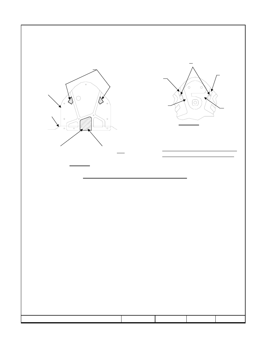
Remove (2) M10 fasteners which secure vehicle cross-bracing members to trunk pan as shown in Figure 2 and return to vehicle
owner.
2.
Remove (4) fascia-mounting bolts which attach fascia to trunk pan as shown in Figure 2. Retain (3) of these bolts for re-
installation (one bolt will not be re-installed and may be returned to vehicle owner). Remove (7) flanged nuts which attach plastic
trunk pan cover to trunk pan. Retain all (7) flanged nuts for re-installation of trunk pan cover.
3.
Remove inboard bumper mounting bolt and flanged nut, one each side, as shown in Figure 1 and return to vehicle owner.
4.
Cut plastic trunk pan cover as shown in Figure 2.
5.
Install M10 x 1.50 x 140mm bolts down thru bumper/bumper mounting bracket, each side, as shown in Figure 1.
Note: There will be sufficient room to use flat wrench to hold bolt head above bumper.
6.
Raise hitch into position as shown. Install conical toothed washers and nuts provided with hitch to M10 fasteners installed in step
5.
7.
Attach forward hitch bar to trunk pan as shown, sandwiching cross-bracing members between hitch bar and trunk pan.
Note: Flat washers must be used as spacers between hitch bar and cross-bracing members.
8.
Re-install (7) flanged nuts which attach trunk pan cover to trunk pan. Reinstall (3) fascia-mounting bolts.
Rev. D
4-24-09
75470N
Sheet 2 of 9
z
2006, 2007, 2009 Cequent Performance Products
Tighten all M10 x 1.50 CL10.9 fasteners with torque wrench to 53 Lb.-Ft. (72 N-M)
Note: check hitch frequently, making sure all fasteners and ball are properly tightened. If hitch is removed, plug all holes in trunk pan or other body panels to
prevent entry of water and exhaust fumes. A hitch or ball which has been damaged should be removed and replaced. Observe safety precautions when working
beneath a vehicle and wear eye protection. Do not cut access or attachment holes with a torch.
This product complies with safety specifications and requirements for connecting devices and towing systems of the state of New York, V.E.S.C. Regulation V-5
and SAE J684.
Form: F205 Rev A 5-6-05
This Fascia-mounting
Bolt will NOT be
Reinstalled after
Hitch installation
Plastic
Fascia
Plastic Trunk
Pan Cover
Figure 2
Cut plastic trunk pan
Cover in area shaded
For hitch bar clearance
Typical all models
Note: Trunk Pan cover requires trimming. Obtain Vehicle Owner’s approval before cutting.
On vehicles without cross bracing members,
This area will need to be cut out to provide
access to trunk pan.
Figure 3
View looking inside vehicle spare
tire well with spare tire and tool kit
removed.
Remove rubber plug
this hole
Inside-vehicle access not necessary on
vehicles with cross bracing members
Rib
¼ x 1 x 3 Block
¼ x 1 x 3 Block
Rib
For Vehicles With Cross Bracing Members
Mercedes-Benz R350
Mercedes-Benz R500
Mercedes-Benz R320 CDI
Mercedes-Benz R320 BlueTEC