Installation instructions – Draw-Tite 75778 MAX-FRAME RECEIVER User Manual
Page 2
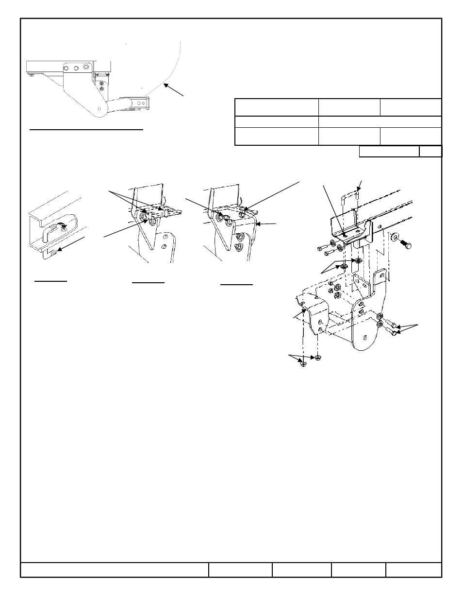
Installation Instructions
Infiniti FX35
Infiniti FX37
Infiniti FX50
Part Numbers:
44692
75778
87639
Hitch Shown In Proper Position
Equipment Required:
Round file, tape, Short Phillips head
Screwdriver, Flat-blade Screwdriver
Wrenches:
10mm, 12mm, 13mm, 14mm, 17mm, 19mm, 9/16”
Drill Bits:
7/16
Fastener Kit:
75778F
Do Not Exceed Lower of Towing Vehicle
Manufacturer’s Rating or
Hitch type
Max Gross
Trailer WT (LB)
Max Tongue
WT (LB)
Weight Distributing
Do Not Use With Spring Bars
Weight Carrying
Ball Mount
4000 (1816 Kg)
400 (182 Kg)
Wiring Access Location:
SUV3, SUV4
Vehicle
Fascia
Accessory Rating
C
Elongate existing
hole in frame
Figure 4
Figure 5
Bolt-on
bracket
U bolt
Figure 6
6
6
6
6
4
4
4
4
4
4
4
4
6
6
6
6
7
7
7
7
1.
Remove splash guards from both driver’s side and passenger’s side wheel wells by removing (3) Phillips head screws and one push pin, each
side, as shown in
figure 2. Retain splash guards and fasteners for reinstallation.
2.
Remove appearance panels from each side by removing push pins and M6 bolts as shown in
figure 3, to access vehicle frame rails. Return
panels and fasteners to vehicle owner.
3.
Remove tow hook from driver’s side frame rail by removing (4) M10 fasteners. Return tow hook and fasteners to vehicle owner.
4.
Remove suspension damper on driver’s side to allow wrench clearance for forward most fastener.
5.
On passenger’s side, remove (2) M8 hex bolts from bottom flange at end of frame rail (located just rearward of exhaust hanger bracket) as
shown and discard.
6.
Raise hitch into position and install fasteners as shown into existing weldnuts, except for bolt on bracket.
7.
With a torque wrench tighten all M8 x 1.25 CL10.9 fasteners to 25 Lb.-Ft. (34 N*M) ; M10 x 1.25 CL8.8 fasteners to 42 Lb.-Ft. (57 N*M);
and all M12 x 1.25 CL8.8 fasteners to 76 Lb.-Ft. (103 N.M)
8.
With hitch installed attached, elongate rear most hole in passenger side frame with drill or file. Approx. 1/8”. Paint bare metal.
9.
Install U bolt as shown in
figure 4 and slide conical washers over the bolt to act as a spacers. Tape them in place until the bracket is installed
see
figure 5.
10.
Install bolt on bracket as shown in
figure 6 with the remaining fasteners noted in the figures.
11.
With a torque wrench tighten U bolt lock nuts to 35 Lb.-Ft. (47 N*M) and 3/8-16 grade 8 fasteners to 45 Lb.-Ft. (61 N*M).
12.
Reinstall suspension damper removed in step 4.
13.
Reinstall splash guards removed in step 1.
z
2013 Cequent Performance Products, Inc.
Sheet 2 of 6
75778N
4-25-13
Rev. A
Note: check hitch frequently, making sure all fasteners and ball are properly tightened. If hitch is removed, plug all holes in trunk pan or other body panels to prevent entry of water and exhaust
fumes. A hitch or ball which has been damaged should be removed and replaced. Observe safety precautions when working beneath a vehicle and wear eye protection. Do not cut access or
attachment holes with a torch.
This product complies with safety specifications and requirements for connecting devices and towing systems of the state of New York, V.E.S.C. Regulation V-5 and SAE J684.
Form: F205 Rev A 5-6-05
Bolt-on bracket
7
7
7
7
8
8
8
8
4
4
4
4
4
4
4
4
9
9
9
9
Printed in Mexico