Draw-Tite 75709 MAX-FRAME RECEIVER User Manual
Installation instructions, Ford edge, Lincoln mkx
Installation Instructions
Ford Edge
(
Excluding Sport Model)
Lincoln MKX
Part Numbers:
75709
87604
44658
Ford Edge
Do Not Exceed Lower of Towing Vehicle
Manufacturer’s Rating or
Rail
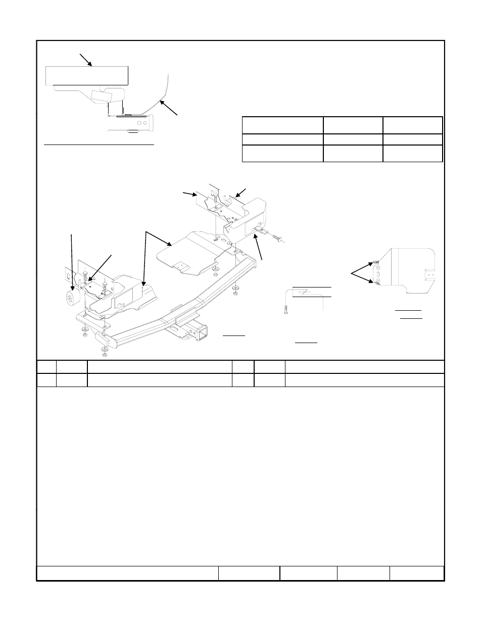
Hitch Shown In Proper Position
Equipment Required: ½” Pull wire (Provided), Tin Snips, Lubricant
or Soapy water
Wrenches: 3/4”, 5.5mm or 7/32, 8mm
Ford Edge
Fascia
Fastener Kit: 75709F
g
Wiring Access Location:
Frame rail
Rubber isolator
Spray some lubricant on the rubber
Hitch type
Max Gross
Trailer WT (LB)
Max Tongue
WT (LB)
Weight Distributing
4000 (1816 Kg)
400 (182 Kg)
Weight Carrying
Ball Mount
3500 (1589 Kg)
350 (159 Kg)
1
4
Frame rail
Access hole at end
of rails
Rubber isolator
Trim both heat shields.
Leave enough to sandwich
between frame and hitch
Forward
hole
p y
exhaust hangers and then use a
screwdriver or pry bar to remove
rubber hangers. Support the
system while you remove all of
the hangers
T i H
Figure 1
2
3
Figure 2
Figure 3
Trim both heat shields.
As shown
Kink Pull wire to keep spacer
independent of bolt
Trim Here
Note: Fasteners typical both sides
1.
Lower exhaust system at the rubber isolator (3 places) leaving the rubber isolator in place on the vehicle. Spraying a lubricant
on the metal hanger rod and the rubber isolator helps removal. Be careful not to allow muffler to fall under its own weight.
2.
Disconnect the fascia center support (1 screw) and carefully push it toward the impact bar and out of the way. Reinstall screw.
3.
Remove both heat shields (3 screws) and a plastic insert each side. Return (4 screws) to owner.
4
Trim both heat shields as shown Figure 2
1
Qty. (4)
Carriage Bolt ½-13 X 1.500 GR5
3
Qty. (4)
Hex Nut ½-13
2
Qty. (4)
Conical Washer
4
Qty. (4)
Spacer ¼ X 1 X 3
Note: Fasteners typical both sides
4.
Trim both heat shields as shown. Figure 2.
5.
Using the kink wire (see Figure 3) method for feeding fasteners attach carriage bolt and block to the pull wire. Feed forward
fasteners into place on both rails using the access hole at the end of the frame rail. On the outside end of both rails there is a
wide notch to make this process easier. Feed rearward fasteners into location using the same method. Note: Make sure
spacer are sitting flat on the rails and not on existing weld nuts.
6.
Replace trimmed heat shields using the remaining inboard fasteners and plastic insert.
7. Raise hitch into position over the exhaust. Sandwiching the heat shield between the hitch and the rail.
8. Loosely attach fasteners as shown, center hitch on vehicle and tighten fastener to 75 Lb.-Ft. (102 N*M).
9. Raise exhaust system (3) places back into position.
z
2010 Cequent Performance Products
Sheet 1 of 3
75709N
9-6-10
Rev. A
Note: check hitch frequently, making sure all fasteners and ball are properly tightened. If hitch is removed, plug all holes in trunk pan or other body panels to
prevent entry of water and exhaust fumes. A hitch or ball which has been damaged should be removed and replaced. Observe safety precautions when working
beneath a vehicle and wear eye protection. Do not cut access or attachment holes with a torch.
This product complies with safety specifications and requirements for connecting devices and towing systems of the state of New York, V.E.S.C. Regulation V-5
and SAE J684.
Form: F205 Rev A 5-6-05