2 connecting bus lines and power supply – BEI Sensors MHK5 Absolute Hollow Shaft Encoder User Manual
Page 6
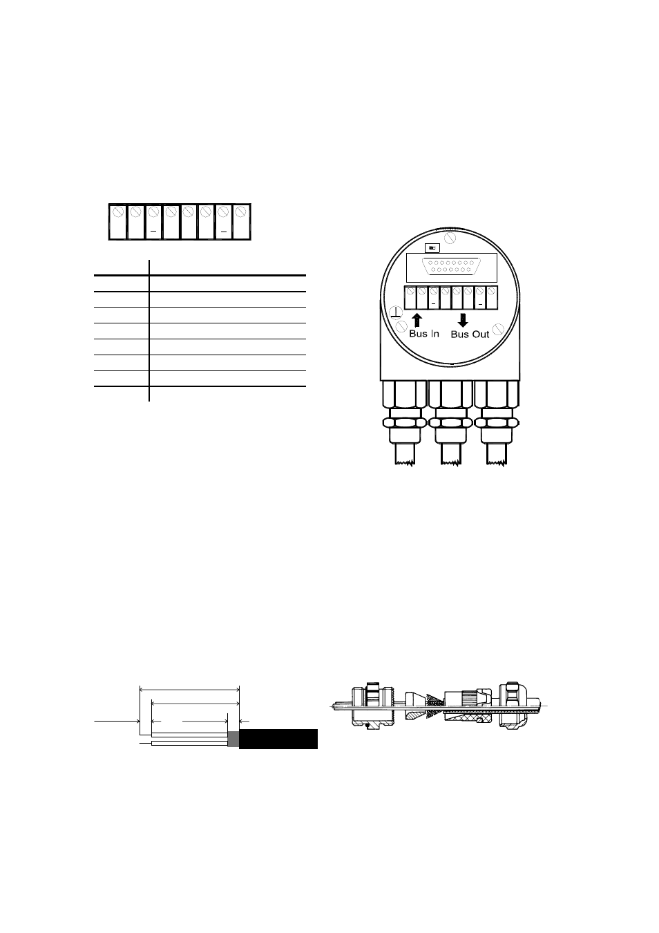
2.2 Connecting bus lines and power supply
A
B
+
B
+
A
Clamp Description
B (left)
Bus line B (Bus in)
A (left)
Bus line A (Bus in)
- 0
V
+
10 – 30 V
B (right)
Bus line B (Bus out)
A (right)
Bus line A (Bus out)
- 0
V
+
10 – 30 V
The power supply has to be connected once (no
matter which clamps). If the terminating resistor is
switched on, the outgoing bus lines are
disconnected.
A
B
A
B
+
+
ON
R
2.3 Connecting-up the connection cap
with cable glands
Remove screw, sealing and cone from the cable
gland. Remove 55 mm of the cable sheath and 50
mm of the shielding. About 5 mm of the wires
should be stripped. Put screw and sealing on the
cable. The cone should be mounted under the
shielding according to the figure. Put the whole
cable into the cable gland and tighten the screw.
Note: If a combined cable (power supply and bus
lines in one cable) is used the large cable diameter
can lead to problems. For these cases offers
connection caps with larger cable glands (refer to
product catalogue).
5 mm
5 mm
55 mm
50 mm
Page 6
BEI Sensors Profibus Manual serie M
Revision 03/10