Digital phosphor oscilloscopes — dpo7000 series – Atec Tektronix-DPO7000 Series User Manual
Page 5
Digital Phosphor Oscilloscopes — DPO7000 Series
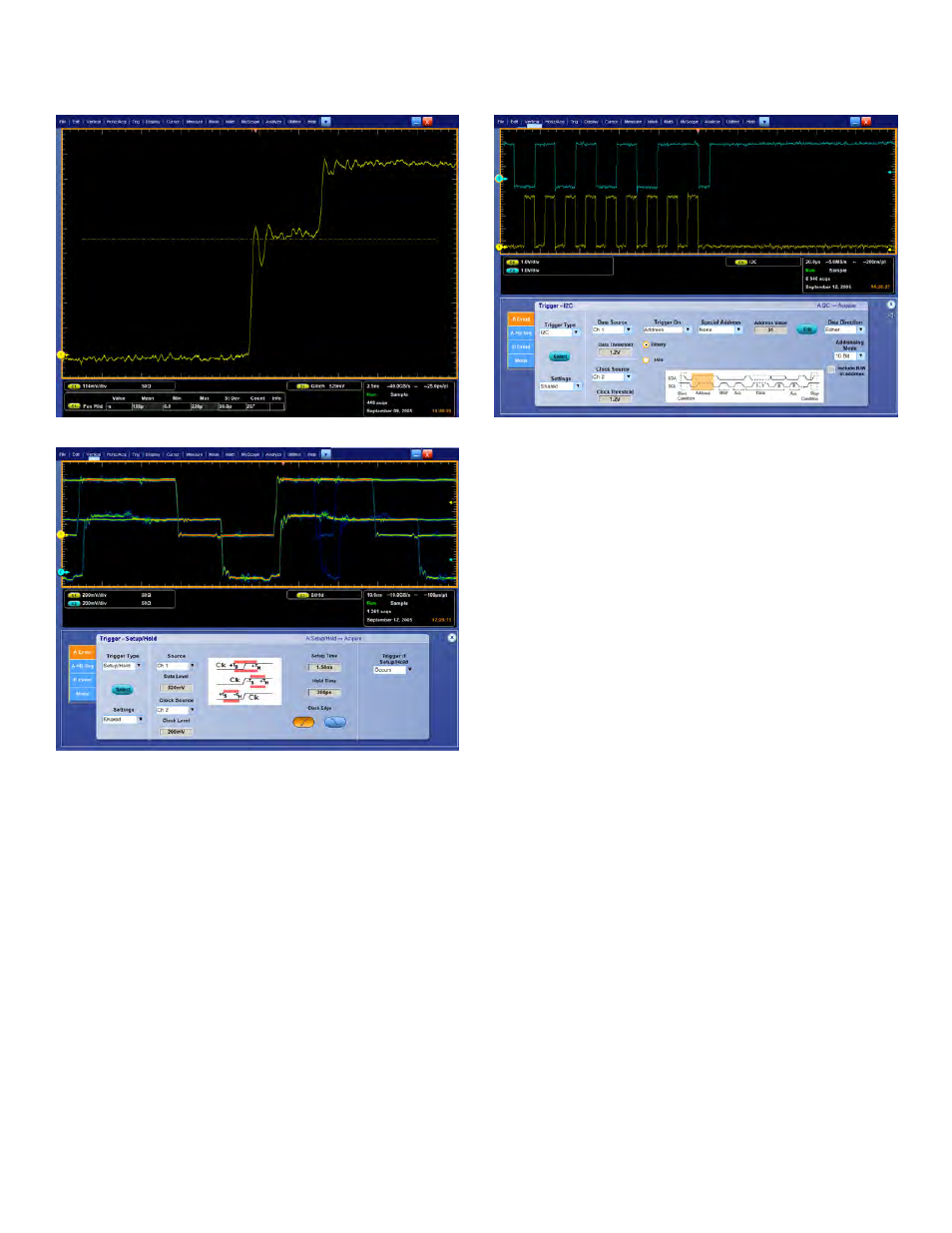
Isolate glitches down to 200 ps wide.
Isolate Setup and Hold violations down to 360 ps.
The Ability to Trigger an Oscilloscope on Events of
Interest is Paramount in Complex Signal Debug and
Validation
Whether you’re trying to find a system error or need to isolate a section
of a complex signal for further analysis, like a DDR Read or Write burst,
Tektronix Pinpoint
®
triggering provides the solution. The Pinpoint trigger
system uses Silicon Germanium (SiGe) technology to provide trigger
sensitivity of up to the bandwidth of the instrument, and allows selection
of most trigger types on both A and B trigger circuits. It can capture very
narrow glitches with very little trigger jitter. Other trigger systems offer
Easily trigger on a specific I
2
C address.
multiple trigger types only on a single event (A event), with delayed trigger
(B event) selection limited to edge-type triggering and often do not provide a
way to reset the trigger sequence if the B event doesn’t occur. But Pinpoint
triggering provides a full suite of advance trigger types on both A and B
triggers with Reset triggering to begin the trigger sequence again after a
specified time, state, or transition so that even events in the most complex
signals can be captured. Other oscilloscopes typically offer less than 20
trigger combinations; Pinpoint triggering offers over 1400 combinations,
all at full performance.
With Enhanced Triggering, you can choose to compensate for the difference
in time there is between the trigger path and the display path and eliminate
virtually any trigger jitter at the trigger point. In this mode, the trigger point
can be used as a measurement reference.
Trigger on the Most Relevant Bit Sequence of the
Industry-standard Serial Bus
I
2
C (Inter-Integrated Circuit) triggering is a standard feature and includes
Start Condition, Missing Acknowledge, Restart, Data Read, Address, and/or
Data Frame, in a 10 bit or 7 bit format with a specific selection to choose
whether or not to include the R/W bit.
SPI (Serial Peripheral Interface) triggering is a standard feature and
includes triggering on a data pattern within a user-definable frame.
RS-232 triggering is a standard feature.
CAN (Controller Area Network) triggering is an optional feature (Opt. LSA)
and includes synchronization to the Start or End of a CAN frame on any
CAN high or CAN low signal, triggering on Type of Frame (Data, Remote,
Overload), Identifier, Data, Missing Acknowledge, and Bit Stuffing error.
www.tektronix.com
5