Measurement range – Atec Rohde-Schwarz-ZNB Series User Manual
Page 4
Version 07.00, August 2013
4
Rohde & Schwarz R&S
®
ZNB Vector Network Analyzer
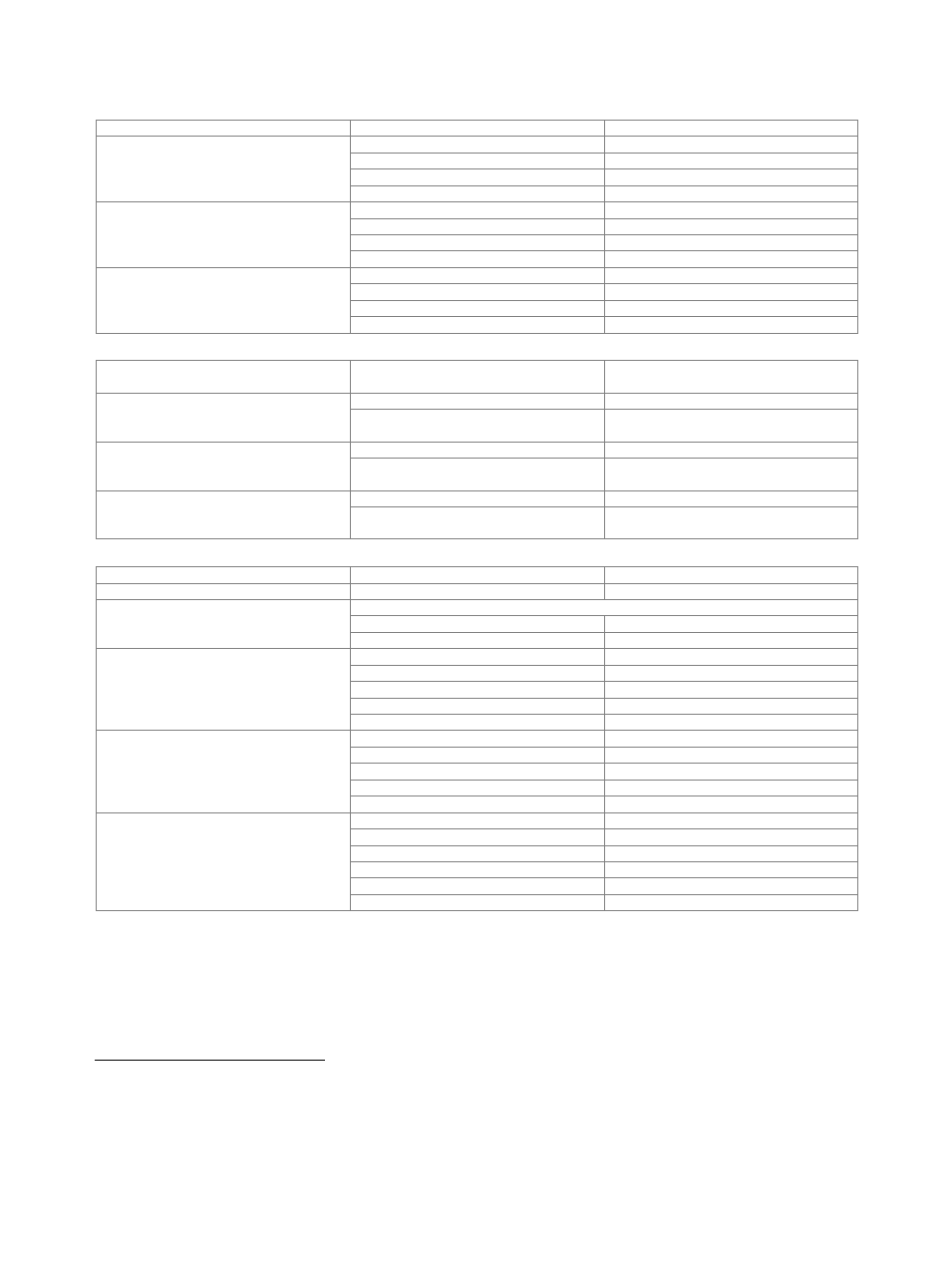
Measurement range
Impedance
50 Ω
Test port connector
R&S
®
ZNB4
N female
R&S
®
ZNB8
N female
R&S
®
ZNB20
3.5 mm, male, ruggedized
R&S
®
ZNB40
2.92 mm, male, ruggedized
Number of test ports
R&S
®
ZNB4
2 or 4
R&S
®
ZNB8
2 or 4
R&S
®
ZNB20
2 or 4
R&S
®
ZNB40
2
Frequency range
R&S
®
ZNB4
9 kHz to 4.5 GHz
R&S
®
ZNB8
9 kHz to 8.5 GHz
R&S
®
ZNB20
100 kHz to 20 GHz
R&S
®
ZNB40
10 MHz to 40 GHz
Static frequency accuracy
(time since last adjustment × aging rate) +
temperature drift + calibration accuracy
Aging per year
standard
±1 × 10
–6
with R&S
®
ZNB-B4 precision frequency
reference option
±1 × 10
–7
Temperature drift (0 °C to +50 °C)
standard
±1 × 10
–6
with R&S
®
ZNB-B4 precision frequency
reference option
±1 × 10
–8
Achievable initial calibration accuracy
standard
±5 × 10
–7
with R&S
®
ZNB-B4 precision frequency
reference option
±5 × 10
–8
Frequency resolution
1 Hz
Number of measurement points
per trace
2 to 100001
Measurement bandwidth
1/1.5/2/3/5/7 steps
without optional increased bandwidth
1 Hz to 1 MHz
with optional increased bandwidth
1 Hz to 10 MHz
Dynamic range
of the R&S
®
ZNB4 and
the R&S
®
ZNB8
(without optional step attenuators)
9 kHz to 100 kHz
> 100 dB, typ. 122 dB
100 kHz to 50 MHz
> 120 dB, typ. 138 dB
50 MHz to 4 GHz
> 130 dB, typ. 140 dB
4 GHz to 7 GHz
> 125 dB, typ. 138 dB
7 GHz to 8.5 GHz
> 120 dB, typ. 130 dB
®
ZNB20
100 kHz to 1 MHz
> 100 dB, typ. 110 dB
1 MHz to 10 MHz
> 110 dB, typ. 120 dB
10 MHz to 100 MHz
> 115 dB, typ. 125 dB
100 MHz to 6 GHz
> 125 dB, typ. 135 dB
6 GHz to 20 GHz
> 120 dB, typ. 130 dB
Dynamic range
®
ZNB40
10 MHz to 50 MHz
> 90 dB, typ. 105 dB
50 MHz to 100 MHz
> 115 dB, typ. 125 dB
100 MHz to 500 MHz
> 120 dB, typ. 130 dB
500 MHz to 20 GHz
> 125 dB, typ. 135 dB
20 GHz to 30 GHz
> 115 dB, typ. 125 dB
30 GHz to 40 GHz
> 110 dB, typ. 120 dB
1
Specified and typical data given in this data sheet applies to the R&S
®
ZNB4, the R&S
®
ZNB8, the R&S
®
ZNB20 and the R&S
®
ZNB40; please note their
respective frequency ranges.
2
The dynamic range is defined as the difference between the actual maximum source power and the RMS value of the data trace of the transmission
magnitude, which is produced by noise and crosstalk with the test ports short-circuited. The specification applies at 10 Hz measurement bandwidth,
without system error correction. The dynamic range can be increased by using a measurement bandwidth of 1 Hz. Crosstalk does not limit the dynamic
range. Dynamic range between port 1 and port 2 and between port 3 and port 4 (4-port model). Otherwise the dynamic range performance is typical.