3 recommended torque values, 4 cabling layout – Alpha Technologies Cordex CXPS-D 48-2500_5000A User Manual
Page 42
-5HY%
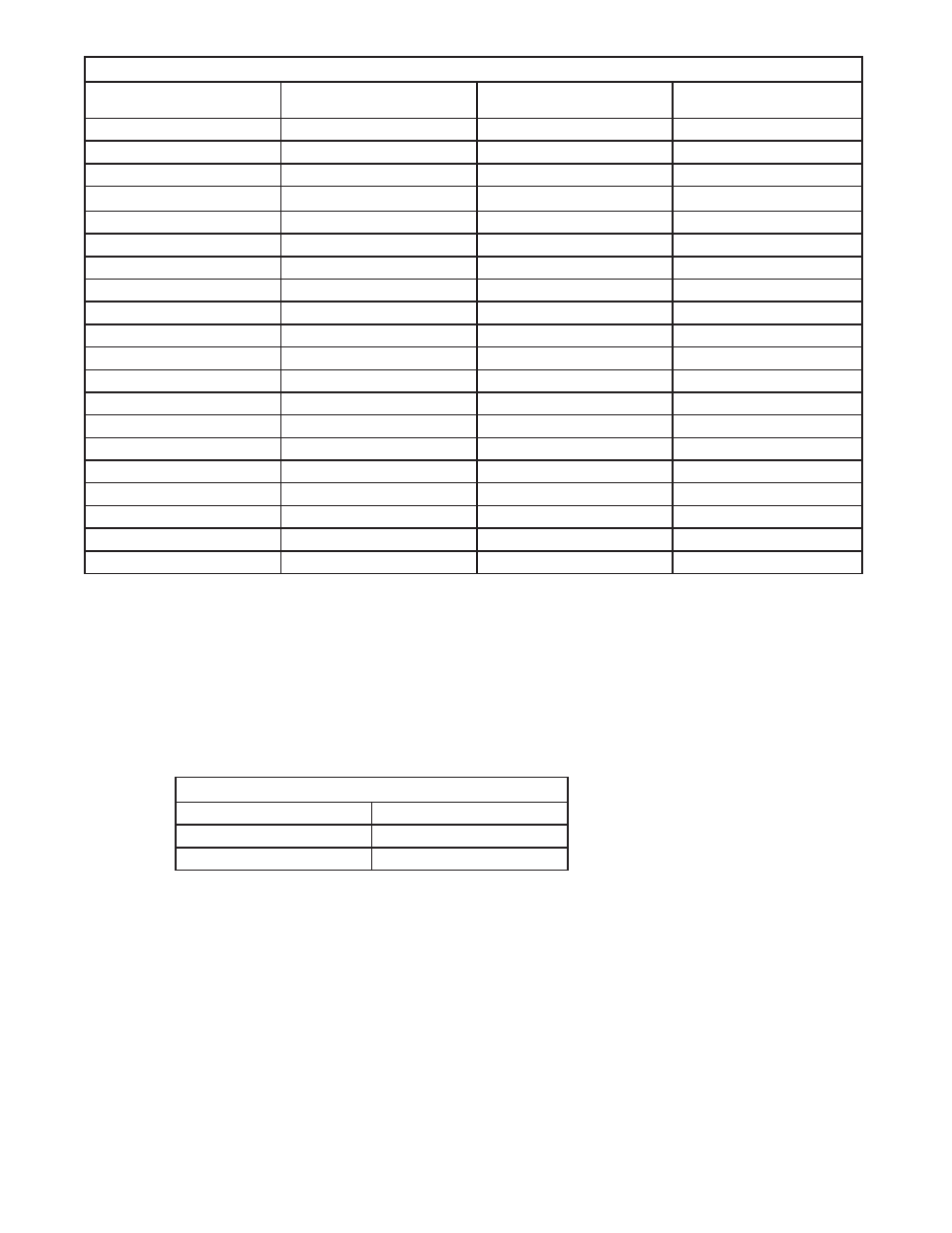
7DEOH' ² &DEOHVL]HHTXLYDOHQWV$:*WR0HWULF
&DEOHVL]HVHHQRWHV
DQG
&LUFXODUPLOV
6TXDUHPLOOLPHWHUV
(TXLYDOHQWPHWULFFDEOH
$:*
$:*
$:*
$:*
$:*
$:*
$:*
$:*
$:*
$:*
$:*RU
RU
$:*RU
$:*RU
0&0RUNFPLO
RU
0&0RUNFPLO
0&0RUNFPLO
RU
0&0RUNFPLO
0&0RUNFPLO
0&0RUNFPLO
0&0RUNFPLO
t
6.1.3 Recommended Torque Values
Recommended torque values for connection to the power system:
»
Clear hole connections (nut and bolt)
»
PEM studs
»
PEM threaded inserts
»
Thread formed connections (in copper bus bar)
7DEOH( ² 5HFRPPHQGHGWRUTXHYDOXHV
IWOEV
IWOEV
IWOEV
Grade 5 rating is required for these torque values.
6.1.4 Cabling
Layout
The cabling at the time of installation is straightforward.
»
The AC cables for the rectifiers connect to the shelves on both sides, and are brought down from
the top of the frame to the rectifier shelves.
»
The battery cables and the external battery return bar connect to the bay at the top rear.
»
The load cables to the distribution modules enter the bay through the top.
»
The load return cables connect to external battery return bar
»
All signaling wires (for example, alarms from the CXC Controller) interfacing with the outside world
exit the frame through the top.