Alpha Technologies Cordex CXPS-D 48-2500_5000A User Manual
Page 35
-5HY%
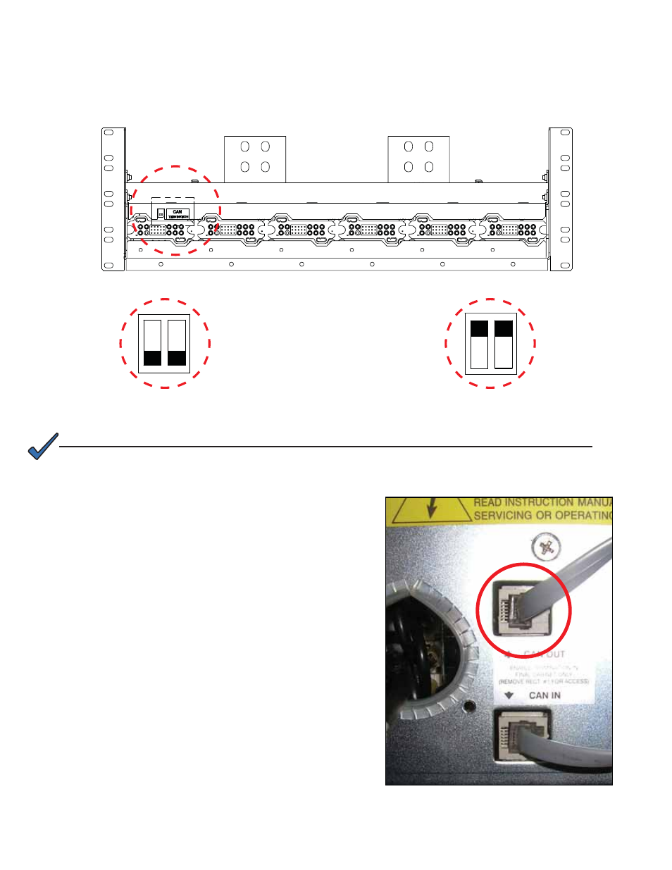
Inter-bay CAN Bus Cable
The CAN bus provides a communication path between the controller and rectifiers. In a single
bay, the CAN bus cabling is daisy-chained from the shunt mux, if installed, to the bottom rectifier
shelf. The cable is then daisy-chained from the bottom shelf, to higher shelves, in sequence. At
the last shelf, termination is enabled—see Figure 18.
&$1WHUPLQDWLRQHQDEOHG
&$1WHUPLQDWLRQGLVDEOHG
)LJXUH ² &$1EXVWHUPLQDWLRQ
1. Remove the left most rectifier in the top shelf of the
existing bay. (Refer to the Rectifier Shelf manual for
the removal and re-insertion procedure.)
2. Flip the DIP switches from Termination Enabled to
Termination Disabled—see Figure 18.
3. Replace the rectifier.
4. Connect the CAN bus cable to the CAN OUT
connector of the top rectifier shelf of the expansion
bay.
)LJXUH ² &$1287FRQQHFWLRQ
127(
,I\RXUV\VWHPKDVUHGXQGDQWUHFWL¿HUVLWLVUHFRPPHQGHGWRSRZHURIIWKHOHIWPRVW
UHFWL¿HULQWKHWRSVKHOIRIWKHH[LVWLQJED\GXULQJWKLVSURFHGXUH